AWK-3121 Quick Installation Guide Moxa AirWorks Fourth Edition, December 2010 2010 Moxa Inc. All rights reserved. Reproduction without permission is prohibited.
Overview Moxa’s AWK-3121 Access Point/Bridge/AP Client is ideal for applications that are hard to wire, too expensive to wire, or use mobile equipment that connects over a TCP/IP network. The AWK-3121 is rated to operate at temperatures ranging from 0 to 60°C for standard models and -40 to 75°C for extended temperature models, and is rugged enough for any harsh industrial environment. Installation is easy, with either DIN-Rail mounting or distribution boxes.
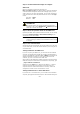
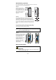
Step 4: Use the web-based manager to configure AWK-3121 Open your computer’s web browser and then type http://192.168.127.253 in the address field to access the homepage of the web-based management. Before the homepage opens, you will need to enter the user name and password. For first-time configuration, enter the default user name and password and then click on the Login button: User name: admin Password: root ATTENTION For security reasons, we strongly recommend changing the password.
the first AWK-3121 connected to notebook A, and change the second or third AWK-3121 connected to notebook B to Client mode and then configure the notebooks and AWK-3121s properly. After setting up the testing environment, open a DOS window on notebook B. At the prompt, type ping IP address of notebook A and then press Enter key. A “Reply from IP address …” response means the communication was successful. A “Request timed out.” response means the communication failed.
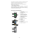
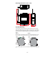
134.00 [5.28"] 135.00 [5.31"] 198.50 [7.81"] Mounting Dimensions (unit = mm) 45.80 [1.80"] 52.98 [2.09"] 105.00 [4.13"] DIN-Rail Mounting The aluminum DIN-Rail attachment plate should be fixed to the back panel of the AWK-3121 when you take it out of the box. If you need to reattach the DIN-Rail attachment plate to the AWK-3121, make sure the stiff metal spring is situated towards the top, as shown in the figures below.
Wall Mounting (optional) For some applications, it may be more convenient to mount the AWK-3121 to a wall, as illustrated below. STEP 1: Remove the aluminum DIN-Rail attachment plate from the AWK-3121, and then attach the wall mount plates with M3 screws, as shown in the adjacent diagrams. top plate bottom plate STEP 2: 6.0 mm Mounting the AWK-3121 to a wall requires 4 screws. Use the AWK-3121 device, with wall mount plates attached, as a guide to mark the correct locations of the 4 screws.
WARNING Safety First! Calculate the maximum possible current in each power wire and common wire. Observe all electrical codes dictating the maximum current allowed for each wire size. If the current goes above the maximum ratings, the wiring could overheat, causing serious damage to your equipment. You should also pay attention to the following items: • • • • Use separate paths to route wiring for power and devices.
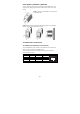
Wiring the Redundant Power Inputs The top two pairs of contacts of the 10-contact terminal block connector on the AWK-3121’s top panel are used for the AWK-3121’s two DC inputs. Top and front views of the terminal block connector is shown here. STEP 1: Insert the negative/positive DC wires into the V-/V+ terminals. STEP 2: To keep the DC wires from pulling loose, use a small flat-blade screwdriver to tighten the wire-clamp screws on the front of the terminal block connector.
Cable Holder Installation (Optional) You can attach the cable holder to the bottom of the AWK-3121. This helps to keep cabling neat and avoid accidents that result from untidy cables. STEP 1: Screw the cable holder onto the bottom of the AWK-3121. STEP 2: After mounting the AWK-3121 and plugging in the LAN cable, tighten the cable along the device and wall.
RS-232 Connection The AWK-3121 has one RS-232 (8-pin RJ45) console port located on the front panel. Use either an RJ45-to-DB9 or RJ45-to-DB25 cable to connect the Moxa AWK-3121’s console port to your PC’s COM port. You may then use a console terminal program to access the AWK-3121 for console configuration. Console Pinouts for 10-pin or 8-pin RJ45 10-Pin Description 8-Pin 1 ----2 DSR 1 3 RTS 2 4 GND 3 5 TxD 4 6 RxD 5 7 DCD 6 8 CTS 7 9 DTR 8 10 ----NOTE 1. 2.
LED Indicators The front panel of the Moxa AWK-3121 contains several LED indicators. The function of each LED is described in the table below. LED Color State Description Front Panel LED Indicators (System) Power is being supplied from power On input 1. PWR1 Green Power is not being supplied from Off power input 1. Power is being supplied from power On input 2. PWR2 Green Power is not being supplied from Off power input 2. On Power is being supplied via PoE.
Specifications WLAN Standards Spread Spectrum and Modulation Operating Channels (Central Frequency) Security Transmission Rates IEEE 802.11a/b/g for Wireless LAN IEEE 802.3u 10/100BaseT(X) for Ethernet LAN IEEE 802.3af for Power-over-Ethernet IEEE 802.1D/w STP/RSTP DSSS with DBPSK, DQPSK, CCK OFDM with BPSK, QPSK, 16QAM, 64QAM US: 2.412 to 2.462 GHz (11 channels) 5.18 to 5.24 GHz (4 channels) EU: 2.412 to 2.472 GHz (13 channels) 5.18 to 5.24 GHz (4 channels) JP: 2.412 to 2.472 GHz (13 channels, OFDM) 2.
RX Sensitivity (for hardware revision 1.0 and 1.1): 802.11b: -92 dBm @ 1 Mbps, -90 dBm @ 2 Mbps, -88 dBm @ 5.5 Mbps, -84 dBm @ 11 Mbps 802.11g: -87 dBm @ 6 Mbps, -86 dBm @ 9 Mbps, -85 dBm @ 12 Mbps, -82 dBm @ 18 Mbps, -80 dBm @ 24 Mbps, -76 dBm @ 36 Mbps, -72 dBm @ 48 Mbps, -70 dBm @ 54 Mbps 802.
ATTENTION The AWK-3121 is NOT a portable mobile device and should be located at least 20 cm away from the human body. The AWK-3121 is NOT designed for the general public. To deploy AWK-3121s and establish a wireless network safely, a well-trained technician is required for installation. ATTENTION Use the antennas correctly: The 2.4 GHz antennas are needed when the AWK-3121 operates in IEEE 802.11b/g. The 5 GHz antennas are needed for IEEE802.11a.