AWK-4131 Hardware Installation Guide Moxa AirWorks First Edition, March 2011 2010 Moxa Inc. All rights reserved. Reproduction without permission is prohibited.
Notes for the Reader WARNING Indicates that death or personal injury may occur if proper precautions are not taken. ATTENTION Indicates that possible damage to this product or your property may result if proper precautions are not taken. NOTE Highlights important information related to this product. Package Checklist Moxa’s AWK-4131 is shipped with the following items. If any of these items is missing or damaged, please contact your customer service representative for assistance.
• • • • • • • • • SFP-1GLXLC-T: Small form factor pluggable transceiver with 1000BaseLX, LC, 10 km, -40 to 85°C SFP-1GLHLC: Small form factor pluggable transceiver with 1000BaseLH, LC, 30 km, 0 to 60°C SFP-1GLHLC-T: Small form factor pluggable transceiver with 1000BaseLH, LC, 30 km, -40 to 85°C SFP-1GLHXLC: Small form factor pluggable transceiver with 1000BaseLHX, LC, 40 km, 0 to 60°C SFP-1GLHXLC-T: Small form factor pluggable transceiver with 1000BaseLHX, LC, 40 km, -40 to 85°C SFP-1GZXLC: Small f
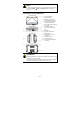
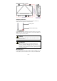
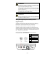
NOTE To make the change effective, you must save the change and then click Restart Save and Restart button to apply all changes. Panel Layout of the AWK-4131 1. 2. 3. 4. 5. 6. 7. 8. 9. 10. 11. 12. 13. Main antenna A. Main antenna B. LEDs for PWR, FAULT, STATE, WLAN and LAN. M12 A-coding connector for PWR1 and PWR2. M12 8-pin male connector for DI/DO M12 8-pin female connector for Ethernet port SFP Port RS-232 console port.
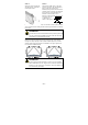
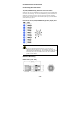
Dimensions (unit = mm) Attaching Antennas The AWK-4131 inclues two dual-band omni-directional antenna by default. Attach the antennas as illustrated below. Rubber plate Antenna Metal N-type Step 1: Use your fingers and hold the antenna metal N-type connector. Step 2: Screw the antenna N-type connector (male) onto the AWK-4131 device’s N-type connector (female) Caution Do not hold the rubber plate to screw the antenna on to the AWK-4131 device. ATTENTION Use the antennas correctly: Use 2.
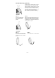
STEP 1: Attach the wall-mounting kit with M4 screws, as shown in the diagram below. STEP 2: Mounting the AWK-4131 on the wall requires 4 screws. Use the AWK-4131 device, with wall-mounting kit attached, as a guide to mark the correct locations of the 4 screws. The heads of the screws are recommended to be between 5.5mm and 8.5 mm in diameter, and the shafts should not be more than 5.0 mm in diameter, as shown in the figure.
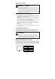
DIN-Rail Mounting (Optional) The DK-DC50131 die-cast metal kit can be bought separately, and enable easy and robust installation for the AWK-4131. A pair of DK-DC50131s is needed for DIN-Rail mounting. To install the DIN-Rail mounting kits, tightly attach the two DIN-Rail mounting kits on the rear panel of AWK-4131 with 12 screws. (6 screws for each kit) To Install STEP 1: Use the recessed button on the spring-loaded bracket to lock it into position.
Wiring Requirements WARNING Safety First! Be sure to disconnect the power cord before installing and/or wiring your Moxa AWK-4131. Calculate the maximum possible current in each power wire and common wire. Observe all electrical codes dictating the maximum current allowable for each wire size. If the current goes above the maximum ratings, the wiring could overheat, causing serious damage to your equipment.
ATTENTION This product is intended to be supplied by a Listed Power Unit marked “Class 2” or “LPS” and rated O/P: 12 to 48 VDC, minimum 6 W (12 V/0.494 A to 48V/0.121 A, 25°C). Make sure External Power Adaptor (includes power cords and plug assemblies) provided with the unit is certified and suitable for use in your country. Before connecting the AWK-4131 to the DC power inputs, make sure the DC power source voltage is stable. ATTENTION Do not use the PoE Injector. Instead, please use an IEEE802.
Communication Connections Connecting the Data Lines 10/100/1000BaseT(X) Ethernet Port Connection AWK-4131 has 10/100/1000BaseT(X) Ethernet ports (8-pin shielded M12 connector with A coding). The 10/100/1000BaseT(X) ports located on the AWK-4131’s bottom panel are used to connect to Ethernet-enabled devices. Below we show pinouts for both MDI (NIC-type) ports and MDI-X (HUB/Switch-type) ports.
Installation 1. 2. 3. Refer to the pin assignment and solder wires with ; Then assemble , , , and in order; Test the plug to ensure the quality. RS-232 Connection The AWK-4131 has one RS-232 (8-pin RJ45) console port located on the bottom panel. Use either an RJ45-to-DB9 or RJ45-to-DB25 cable to connect the Moxa AWK-4131’s console port to your PC’s COM port. You may then use a console terminal program to access the AWK-4131 for console configuration.
LED State Blinking (fast) Off STATE Green/Red Green Green, blinking Red WLAN Green/ Green, on Amber Green, blinking Amber, on Amber, blinking Off LAN Color Amber/ Green Description IP address conflict (interval: 0.5 sec) Error condition does not exist. Software Ready The AWK has been located by AWK Search Utility. (interval: 1sec) Booting or Error condition WLAN functions in Client mode. WLAN’s data communication is run in Client/Slave mode WLAN functions in AP/Bridge mode.
Security: Transmission Rates: TX Transmit Power: TX Transmit Power MIMO: RX Sensitivity: Protocol Support General Protocols: AP-only Protocols: 5.18 to 5.24 GHz (4 channels for W52) • SSID broadcast enable/disable • Firewall for MAC/IP/Protocol/Port-based filtering • 64-bit and 128-bit WEP encryption, WPA/WPA2-Personal and Enterprise (IEEE 802.1X/RADIUS, TKIP and AES) 802.11b: 1, 2, 5.5, 11 Mbps 802.11a/g: 6, 9, 12, 18, 24, 36, 48, 54 Mbps 802.11n: 6 to 300 Mbps (multiple rates supported) 802.
LAN Ports: 1, 10/100/1000BaseT(X), auto negotiation speed (M12 female type) Fiber Ports: 1, 1000BaseSFP slot Console Port: RS-232 (waterproof RJ45-type) LED Indicators: PWR, FAULT, STATE, WLAN, LAN Alarm Contact (digital 1 relay output with current carrying capacity of 1 A @ 24 VDC output, M12 male connector): Digital Inputs (M12 • +13 to +30 V for state “1” connector): 2 • +3 to -30 V for state “0” electrically isolated • Max.