AWK-4252A Series Quick Installation Guide Moxa AirWorks Version 1.0, September 2022 Technical Support Contact Information www.moxa.com/support 2022 Moxa Inc. All rights reserved.
Overview The AWK-4252A Series is an industrial-grade AP/bridge/client with IEEE 802.11ac Wave 2 technology. This Series features concurrent dual-band Wi-Fi data transmissions up to 400 Mbps (2.4 GHz mode) and 867 Mbps (5 GHz mode) simultaneously, meeting the speed and flexibility requirements for industrial applications. In addition, the built-in dual band pass filter and the wide-temperature design ensure the reliability and continuous operation in harsh environments.
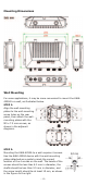
Panel Layout of the AWK-4252A 1. 2. 3. 4. 5. 6. 7. 8. 9. 10. 11. 12. -3- Antenna connector 2 Antenna connector 1 System LEDs: PWR, LAN2, LAN1, 2.
Mounting Dimensions Wall Mounting For some applications, it may be more convenient to mount the AWK4252A to a wall, as illustrated below. STEP 1: Align the wall-mounting plates to the wall-mounting screw holes on the rear panel, then attach the wallmounting plates with the M5 x 7.5 mm screws, as shown in the adjacent diagrams. STEP 2: Mounting the AWK-4252A to a wall requires 4 screws.
Do not drive the screws in all the way—leave a space of about 2 mm to allow room for sliding the wall-mounting panel between the wall and the screws. NOTE Test the screw head and shank size by inserting the screws into one of the keyhole shaped apertures of the wall-mounting plates before they are fixed to the wall.
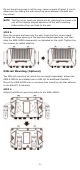
STEP 2: STEP 3: Insert the upper lip of the DIN-rail Press the AWK-4252A towards the kit into the mounting rail. mounting rail until it snaps into place. To remove the AWK-4252A from the DIN rail, do the following: STEP 1: Pull down the latch on the DIN-rail kit with a screwdriver. STEP 2 & 3: Slightly pull the AWK-4252A forward and lift it up to remove it from the mounting rail.
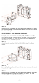
STEP 2: Install the AWK-4252A with the mount assembled on a pole and fasten the screws M8 screws on the bracket of the pole-mounting kit to secure the device to the pole. PK-DC2DOF-02 Pole Mounting (Optional) It may be more convenient to mount the AWK-4252A on a pole for some applications, as illustrated below. The edges of the iron rings on the pole-mounting kit are sharp. We recommend wearing protective gloves during the installation process.
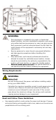
WARNING • • • • This equipment is intended to be used in a Restricted Access Location, such as a dedicated computer room where only authorized service personnel or users can gain access. Such personnel must be instructed about the fact that the metal chassis of the equipment is extremely hot and may cause burns. Service personnel or users have to pay special attention and take special precautions before handling this equipment.
NOTE • • • Do not run signal or communications wiring and power wiring in the same wire conduit. To avoid interference, wires with different signal characteristics should be routed separately. You can use the type of signal transmitted through a wire to determine which wires should be kept separate. The rule of thumb is that wiring that shares similar electrical characteristics can be bundled together. Keep input wiring and output wiring separated.
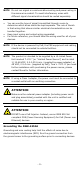
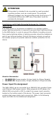
ATTENTION This product is intended to be mounted to a well-grounded mounting surface, such as a metal panel. The potential difference between any two grounding points must be zero. If the potential difference is NOT zero, the product could be permanently damaged. Installations with Cable Extended Antennas for Outdoor Applications If an AWK device or its antenna is installed in an outdoor location, proper lightning protection is required to prevent direct lightning strikes to the AWK device.
Pin 1 2 3 4 5 Power Input V1+ V2+ V1V2GND ATTENTION If the AWK-4252A is connected to a motor or other similar type of equipment, be sure to use power isolation protection. Before connecting the AWK-4252A to the DC power inputs, make sure the DC power source voltage is stable. Wiring the Digital Inputs and Relay Contact (Digital Output) The AWK-4252A has two sets of digital input—DI1 and DI2. Each DI comprises of two contacts of the 8-pin M12 connector on the AWK4252A’s bottom panel.
Communication Connections 10/100/1000BaseT(X) Ethernet Port Connection The 10/100/1000BaseT(X) ports located on the AWK-4252A’s front panel are used to connect to Ethernet-enabled devices. MDI/MDI-X Port Pinouts Pin 1 2 3 4 5 6 7 8 1000BaseT 10/100BaseT 10/100BaseT MDI/MDI-X (X) (X) MDI MDI-X TRD(0)+ TX+ RX+ TRD(0)– TXRXTRD(1)+ RX+ TX+ TRD(2)+ – – TRD(2)– – TRD(1)RXTXTRD(3)+ – – TRD(3)– – RS-232 Connection The AWK-4252A has one RS-232 (8-pin RJ45) console port located on the front panel.
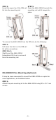
Installation STEP 1: Attach the gasket ① to the housing ③ STEP 2: Insert the cable (e.g., CAT5e) through the clamp ring ④, screw nut ②, seal ⑤ and housing ③, as follows: STEP 3: Crimp the modular RJ plug to the cable. Note that the use of a snagless cover shield or a strain-relief boot is not recommended here.
LED Indicators The front panel of the AWK-4252A contains several LED indicators. The function of each LED is described in the table below: LED PWR1 LAN2 LAN1 2.4G 5G SYS Color State Description Front Panel LED Indicators (System) Power is being supplied from power On input 1, 2, or PoE. Green Off Power is not being supplied. On LAN port’s 1000 Mbps link is active. Blinking Data is being transmitted at 1000 Mbps. Green Off LAN port’s 1000 Mbps link is inactive. On LAN port’s 100 Mbps link is active.
Specifications Input Current Input Voltage Power Consumption Operating Temperature Storage Temperature NOTE 12-48 VDC, 2.2-0.5 A 12 to 48 VDC, redundant dual power inputs, 48 VDC Power over Ethernet 28 W (max.) Wide Temp. Models: -40 to 75°C (-40 to 167°F) -40 to 85°C (-40 to 185°F) To meet the standard for IP68 protection, all unused ports should be covered with the protective caps. ATTENTION The AWK-4252A is NOT a portable mobile device and should be located at least 20 cm away from the human body.
NOTE For installation flexibility, you can use either antenna 1 or antenna 2. Make sure the antenna connection matches the antennas configured in the AWK-4252A web interface. To protect the connectors and RF module, all radio ports should be terminated by either an antenna or a terminator. We strongly recommend using resistive terminators for terminating the unused antenna ports. Software Setup This section covers the software setup for the AWK-4252A.
Step 4: Access the homepage of the AWK. Open your computer’s web browser and type https://192.168.127.253 in the address field to access the AWK’s homepage. If successfully connected, the AWK’s interface homepage will appear. Click NEXT. Step 5: Choose your country or region. Select your country or region from the drop-down list and click NEXT.
Step 6: Create a user account and password. Enter the username, password, and email address for your user account and click CREATE. NOTE The username and password are case-sensitive. After creating your account, you will be automatically redirected to the login screen.
Step 7: Log in to the device. Enter your username and password and click LOG IN. The device will start initializing, this may take several seconds. Once the warning message has disappeared, you can log in using your username and password. . First-time Quick Configuration After successfully accessing the AWK, refer to the appropriate subsection below to quickly set up a wireless network. NOTE Ensure that there are no IP address conflicts when you configure more than one AWK on the same subnet.
Configuring the AWK as an AP Step 1: Set the operation mode of the AWK to AP mode. Go to Wi-Fi Wireless Settings and select AP from the Operation Mode drop-down list. Step 2: Set up the AWK as an AP. Click the ADD icon to create a new SSID. On the settings page, configure the SSID Status, SSID, RF Band, RTS/CTS Threshold, and Transmission Rate for the 5 GHz or 2.4 GHz band. When finished, click NEXT.
On the second SSID Settings screen, configure the SSID Broadcast Status and Security type. From here, you can also copy the configuration over to the second SSID. When finished, click CONFIRM. Configuring the AWK as a Client Set the operation mode of the AWK to Client mode. Go to Wi-Fi Wireless Settings and select Client from the Operation Mode drop-down list, set the SSID, and click Apply. For more detailed configurations, refer to the AWK-4252A User’s Manual.
Master/slave Mode Configuring the AWK as a Master Step 1: Set the operation mode of the AWK to Master mode. Go to Wi-Fi Wireless Settings and select Master from the Operation Mode drop-down list. Step 2: Set up the AWK as a Master. Click the ADD icon to create a new SSID.
On the settings page, configure the SSID Status, Master/AP (select Master),SSID, RF Band, RTS/CTS Threshold, and Transmission Rate for the 5 GHz or 2.4 GHz band. When finished, click NEXT. On the second SSID Settings screen, configure the SSID Broadcast Status and Security type. From here, you can also copy the configuration over to the second SSID. When finished, click CONFIRM.
Configuring the AWK as a Slave Set the operation mode of the AWK to Slave mode. Go to Wi-Fi Wireless Settings and select Slave from the Operation Mode drop-down list, set the SSID, and click Apply. For more detailed configurations, refer to the AWK-4252A User’s Manual. Certifications FCC/IC Statements Federal Communication Commission Interference Statement This equipment has been tested and found to comply with the limits for a Class A digital device, pursuant to Part 15 of the FCC Rules.
Radio Transmitters (Part 15) This device complies with part 15 of the FCC Rules. Operation is subject to the following two conditions: 1. This device may not cause harmful interference. 2. This device must accept any interference received, including interference that may cause undesired operation. IMPORTANT NOTE This device is restricted to mobile configuration.
Cet appareil a également été évalué et montré conforme aux limites d'exposition RF ISED dans des conditions d'exposition mobiles. (Les antennes sont à plus de 50 cm du corps d'une personne). NCC Statements 經型式認證合格之低功率射頻電機,非經許可,公司、商號或使用者均不得擅自變 更頻率、加大功率或變更原設計之特性及功能。 低功率射頻電機之使用不得影響飛航安全及干擾合法通信;經發現有干擾現象時, 應立即停用,並改善至無干擾時方得繼續使用。 前項合法通信,指依電信法規定作業之無線電通信。低功率射頻電機須忍受合法通 信或工業、科學及醫療用電波輻射性電機設備之干擾。 應避免影響附近雷達系統之操作。高增益指向性天線只得應用於固定式點對點系 統。 KC Statements 이 기기는 업무용 환경에서 사용할 목적으로 적합성평가를 받은 기기로서가정용 환경에서 사용하는 경우 전파간섭의 우려가 있습니다.