Moxa AirWorks AWK-6222 Quick Installation Guide First Edition, October 2009 © 2009 Moxa Inc. All rights reserved. Reproduction without permission is prohibited.
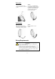
Notes for the Reader WARNING Indicates that death or personal injury may occur if proper precautions are not taken. ATTENTION Indicates that possible damage to this product or your property may result if proper precautions are not taken. NOTE Highlights important information related to this product. Package Checklist Moxa’s AWK-6222 is shipped with the following items. If any of these items is missing or damaged, please contact your customer service representative for assistance.
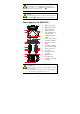
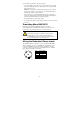
ATTENTION For security reasons, we strongly recommend changing the password. To do so, go to Maintenance Æ Password, and then follow the on-screen instructions. NOTE To make the change effective, you must save the change and then click Restart Æ Save and Restart button to apply all changes. Panel Layout of the AWK-6222 Top Panel View Front Panel View 1 2 3 4 1. MAIN 1 antenna port. 2. MAIN 2 antenna port. 3. AUX 1 antenna port. 4. AUX 2 antenna port. 5.
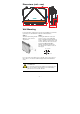
in in Dimensions (unit = mm) in in in Wall Mounting In most applications, wall mount provides an easier installation. You will find it quite easy to mount AWK-6222 on the wall, as illustrated below. STEP 1: STEP 2: Attach the wall-mounting kit with M4 screws, as shown in the diagram below. Mounting the AWK-6222 on the wall requires 4 screws. Use the AWK-6222 device, with wall-mounting kit attached, as a guide to mark the correct locations of the 4 screws.
STEP 3: Once the screws are fixed into the wall, insert the four screw heads through the large opening of the keyhole-shaped apertures, and then slide the AWK-6222 downwards, as indicated to the right. Tighten the four screws for added stability. ⇒ ATTENTION To avoid environmental vibration or shock, you can consider a robust installation with four larger screws, in which the shafts are between 7.0 mm and 8.5 mm in diameter, and fix the AWK-6222 onto wall directly and tightly.
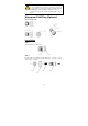
To Install STEP 1: STEP 2: Use the recessed button on the spring-loaded bracket to lock it into position. Insert the top of the DIN-Rail into the slot just below the upper hook of the DIN-Rail mounting kit. Push the AWK-6222 toward the DIN-Rail until the DIN-Rail attachment bracket snaps into place. To Release STEP 1: STEP 2: Pull out the two spring-loaded brackets from the bottom until they are fixed in the “release” position. Pull the AWK-6222 out and upward.
You should also pay attention to the following items: y Use separate paths to route wiring for power and devices. If power wiring and device wiring paths must cross, make sure the wires are perpendicular at the intersection point. NOTE: Do not run signal or communications wiring and power wiring in the same wire conduit. To avoid interference, wires with different signal characteristics should be routed separately.
ATTENTION This product is intended to be supplied by a Listed Power Unit marked “Class 2” or “LPS” and rated O/P: 12 to 48 VDC, minimum 6 W (12 V/0.494 A to 48V/0.121 A). Make sure the External Power Adaptor (including power cords and plug assemblies) provided with the unit is certified and suitable for use in your country. Before connecting the AWK-6222 to the DC power inputs, make sure the DC power source voltage is stable. Please also note, the PoE networks can not route to the outside plant.
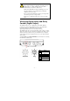
Communication Connections 10/100BaseT(X) Ethernet Port Connection The 10/100BaseT(X) ports located on the AWK-6222’s bottom panel are used to connect to Ethernet-enabled devices. The pinouts for both MDI (NIC-type) ports and MDI-X (HUB/Switch-type) ports are shown below. MDI Port Pinouts Pin 1 2 3 6 MDI-X Port Pinouts Signal Tx+ TxRx+ Rx- Pin 1 2 3 6 8-pin RJ45 Signal Rx+ RxTx+ Tx- 1 8 RS-232 Connection The AWK-6222 has one RS-232 (8-pin RJ45) console port located on the bottom panel.
ATTENTION To ensure the IP68-rated connectivity, you must use a waterproof housing during any communication activities. An IP68-rated field installable plug, which is attached in AWK-6222’s accessory pack, may be needed in this case. The installation guide is shown below: Waterproof RJ45 Plug (Optional) Dimensions (unit: mm) Installation STEP 1: Attach the gasket ① to the housing ③ STEP 2: Insert the cable (ex.
STEP 3: Crimp the modular RJ plug to the cable; (NOTE: the snagless cover shield and strain-relief boot are not recommended.) Then, assemble the seals and the housing (③ and ⑤). STEP 4: Tightly screw the clamp ring ④ to the housing and check to make sure that the plug is securely fastened. (NOTE: for a tighter connection, you can connect the RJ-45 plug to the AWK-6222 before STEP 4.) LED Indicators The front panel of the Moxa AWK-6222 contains several LED indicators.
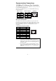
WLAN 2 Green/ Amber Green On WLAN is functioning in Client/Slave mode. Green Blink WLAN’s is transmitting data in Client/Slave mode. Amber On WLAN is functioning in AP/Bridge/Master mode. Amber Blink WLAN’s is transmitting data in AP/Bridge/Master mode. Off WLAN is not in use or not working properly. Yellow On LAN port’s 10Mbps link is active. Yellow Blink Data is being transmitted at 10 Mbps. LAN 1 Yellow/ Green Yellow Off LAN port’s 10Mbps link is inactive.
Protocol General Protocols: Proxy ARP, DNS, HTTP, HTTPS, IP, ICMP, SNTP, TCP, UDP, RADIUS, SNMP, RTP, PPPoE, DHCP AP-only Protocols: ARP, BOOTP, DHCP, dynamic VLAN-Tags for 802.1X-Clients, STP/RSTP (IEEE 802.1D/w) Data Rates 802.11b: 1, 2, 5.5, 11 Mbps 802.11a/g: 6, 9, 12, 18, 24, 36, 48, 54 Mbps 802.11b: Typ. 23±1.5 dBm @ 1 to 11 Mbps 802.11g: Typ. 18±1.5 dBm @ 6 to 24 Mbps, Typ. 16±1.5 dBm @ 36 to 48 Mbps, Typ. 15±1.5 dBm @ 54 Mbps 802.11a: Typ. 20±1.5 dBm @ 6 to 24 Mbps, Typ. 19±1.
Reverse Polarity Protection Mechanical Casing Dimensions Weight Installation Environmental Operating Temperature Storage Temperature Ambient Relative Humidity Present IP68 protection, aluminum case 224 x 147.7 x 66.5 mm (8.82 x 5.82 x 2.62 in) 1.
Technical Support Contact Information www.moxa.