DA-681 Series Embedded Computer Hardware User’s Manual Fifth Edition, January 2010 www.moxa.com/product © 2010 Moxa Inc. All rights reserved. Reproduction without permission is prohibited.
DA-681 Series Embedded Computer Hardware User’s Manual Any software described in this manual is furnished under a license agreement and may be used only in accordance with the terms of that agreement. Copyright Notice Copyright © 2010 Moxa Inc. All rights reserved. Reproduction without permission is prohibited. Trademarks MOXA is a registered trademark of Moxa Inc. All other trademarks or registered marks in this manual belong to their respective manufacturers.
Table of Contents Chapter 1 Introduction ..................................................................................................1-1 Overview.................................................................................................................................. 1-2 Model Descriptions and Package Checklist............................................................................. 1-2 Appearance ............................................................................................
Exiting the BIOS Setup.......................................................................................................... 3-16 Upgrading the BIOS .............................................................................................................. 3-17 Appendix A Safety Installation Instructions.................................................................. A-1 Appendix B Regulatory Statement Approval ................................................................
1 Chapter 1 Introduction Thank you for purchasing the Moxa DA-681 series x86-based industrial ready-to-run embedded computer. This manual introduces the hardware installation, connector interfaces and BIOS setup of the DA-681. For software configuration and management, please refer to the user’s manual for your operating system.
DA-681 Series Hardware User’s Manual Introduction Overview The DA-681 computer is based on the Intel x86 processor and supports VGA, 6 Ethernet ports, 4 RS-232 and 8 RS-485 serial ports with optical isolation, CompactFlash, and USB. The DA-681 comes in a standard 19-inch, 1U high form factor, making it an ideal platform for industrial applications.
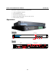
DA-681 Series Hardware User’s Manual Introduction Each model is shipped with following standard items: y 1 DA-681 Embedded Computer y Quick Installation Guide y Documentation & Software CD y Ethernet Cable: RJ45 to RJ45 cross-over cable, 100 cm y Product Warranty Statement Appearance Front View LED Indicators Power Fail 1 Power Storage 19-inch Rackmount Ear RS-232 RS-485 Power Fail 2 LAN LED Indicators LED Indicators Rear View USB 2.
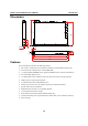
DA-681 Series Hardware User’s Manual Introduction 31.80 44 11.9 6.3 16.
DA-681 Series Hardware User’s Manual Introduction ATTENTION Refer to the “Non-standard Baudrates” section for instructions on how to calculate which baudrates are supported.
DA-681 Series Hardware User’s Manual Introduction Hardware Specifications DA-681-CE Computer CPU OS (pre-installed) DA-681-LX Intel Celeron M 1 GHz processor WinCE 6.0 Linux 2.6 DA-681-XPE Windows XP Embedded SP3 System Chipset FSB BIOS System Memory Intel 910GMLE + ICH6M chipset 400 MHz 4 mega-bit Flash BIOS, PCI Plug & Play, ACPI function support 1 x 200-pin DDR2 SODIMM socket supporting DDR2 400; up to 1 GB max.
DA-681 Series Hardware User’s Manual Flow Control Baudrate Serial Signals RS-232 RS-485-2w LEDs System LAN Serial Physical Characteristics Enclosure Weight Dimensions Mounting Switches and Buttons Reset Button Environmental Limits Operating Temperature Operating Humidity Storage Temperature Anti-Vibration Anti-Shock Power Requirements Input Voltage Power Consumption Input Rating Regulatory Approvals EMC Safety Reliability Alert Tools Warranty Warranty Period Introduction RTS/CTS, XON/XOFF, ADDC™ (automati
DA-681 Series Hardware User’s Manual Introduction Non-standard Baudrates Moxa’s UART ASIC, supports most non-standard baudrates in the range 50 bps to 921.6 Kbps. In fact, supported baudrates are much denser towards the lower values. For example, no baudrates are supported between the integers 5320 and 5323, but 49 baudrates are supported between the integers 387 and 388. Of course this is the way it should be, since serial devices that require using non-standard baudrates generally use slower baudrates.
DA-681 Series Hardware User’s Manual Introduction WARNING Communication between a serial device and a Moxa UART port may not work correctly if the serial device uses a baudrate that it not within the correct tolerance of a baudrate calculated from either formula A or formula B.
2 Chapter 2 Hardware Installation The DA-681 Series of embedded computers are compact and rugged, making them suitable for industrial applications. The LED indicators allow users to monitor performance and identify trouble spots quickly, and multiple ports are provided for connecting a variety of different devices. The DA-681 embedded computers come with a reliable and stable hardware platform that lets you devote the bulk of your time to application development.
DA-681 Series Hardware User’s Manual Hardware Installation Placement Options Desktop Place your DA-681 on a clean, flat, well-ventilated desktop. For better ventilation, leave some space between the DA-681 and other equipment. Do not place equipment or objects on top of the DA-681, as this might damage the computer’s internal components. Rack mounting The DA-681 has rackmount supports for installing the embedded computer on a standard rack. ATTENTIONS 1. 2.
DA-681 Series Hardware User’s Manual Hardware Installation Step 2: Installing the rackmount ears to the DA-681. Use 6 screws to attach one rackmount ear to one side of the DA-681. Repeat this procedure for the ear on the other side of the DA-681. Step 3: Installing the DA-681 to a rack. Gently slide the DA-681 onto the rack, and then use screws provided by the rack supplier to fix the rackmount support to the rail. Note that four screws are required to attach the DA-681 to the rack.
DA-681 Series Hardware User’s Manual Hardware Installation As a final check, make sure that the four screws are firmly attached to the rack. Wiring Requirements The following common safety precautions should be observed before installing any electronic device: y Use separate paths to route wiring for power and devices. If power wiring and device wiring paths must cross, make sure the wires are perpendicular at the intersection point.
DA-681 Series Hardware User’s Manual Hardware Installation Connecting the Power The DA-681 offers both single power and dual power inputs. Use a screwdriver to remove the screws. Connect the power cord to the screws and then attach the screws to the unit. For single models (SP), use Power 1 only; for dual power models (DP and DPP-T), use both Power 1 and Power 2 for power input installation. Refer to the following figure for detailed information.
DA-681 Series Hardware User’s Manual Hardware Installation Wiring the Power Inputs For SP Models PWR 1 +L NC N NC NC NC NC NC NC Power 1 +L N Chasis Ground AC Terminal Protection Earth (Green & Yellow) Line (Black) Bond Earth (Green) Neutral (White) DC Terminal Protection Earth (Green & Yellow) DC + (Black) DC (White) 2-6
DA-681 Series Hardware User’s Manual Hardware Installation For DP Models PWR 1 +L PWR 2 NC NC N +L NC NC N Power 2 Power 1 Chasis Ground +L +L N N Chasis Ground AC Terminal Protection earth (Green & Yellow) Line (Black) Neutral (White) Bond Earth (Green) DC Terminal Protection earth (Green & Yellow) DC + (Black) DC (White) 2-7
DA-681 Series Hardware User’s Manual Hardware Installation For DPP-T Models PWR 1 PWR 2 +L NC +L N NC N Power 1 Surge Ground Power 2 Chasis Ground +L +L N N Chasis Ground Surge Ground AC Terminal Protection earth (Green & Yellow) Line (Black) Neutral (White) Bond Earth (Green) DC Terminal Protection earth (Green & Yellow) DC + (Black) DC (White) 2-8
DA-681 Series Hardware User’s Manual Hardware Installation Power Input Wiring Description Read the following section for a detailed power input wiring description.
DA-681 Series Hardware User’s Manual Hardware Installation 8 PWR2 Surge Ground 9 PWR2 Line/ DC + 10 PWR2 Neutral / DC – supply surge grounds via a removable jumper. PWR2 Surge Ground is connected to the Chassis Ground via a jumper on the terminal block. Surge Ground is used as the ground conductor for all surge and transient suppression circuitry. NOTE: Surge Ground must be disconnected from Chassis Ground during HIPOT (dielectric strength) testing.
DA-681 Series Hardware User’s Manual Hardware Installation For DC Power Input The DA-681 series low voltage DC power supply features reverse polarity protection and dual independent inputs. The dual power inputs allow the connection of two DC sources with the same nominal voltage to provide redundant power supply inputs. The DC source must be connected to the DC inputs according to the polarity markings on the unit. ATTENTION 1.
DA-681 Series Hardware User’s Manual Hardware Installation When finished, press the Power Switch button to start the system. It will take about 30 to 60 seconds for your operating system to boot up. Power Switch Reset Button Pressing the Reset button initiates a hardware warm reboot. The button plays the same role as a desktop PC’s reset button. After pressing the reset button, the system will reboot automatically. During normal use, you should NOT use the Reset Button.
DA-681 Series Hardware User’s Manual Hardware Installation Connecting to a Display Your DA-681 embedded computer comes with a D-Sub 15-pin female connector to connect to the VGA monitor. Be sure to remove the power before you connect or disconnect the monitor cable. VGA 5 1 10 6 15 11 Pin No.
DA-681 Series Hardware User’s Manual Hardware Installation Use the Y-type cable to convert the mini-DIN connector into two 6-pin mini-DIN connectors to connect both a PS/2 keyboard and PS/2 mouse at the same time. (The Y-type cable is not included in the accessory package. It should be purchased separately. You may also use the USB ports to connect your USB-based keyboard and mouse.) ATTENTION Please note that without the Y-type cable, the PS/2 connector on the DA-681 can only work with a PS/2 keyboard.
DA-681 Series Hardware User’s Manual 8 1 LED Ethernet Port 100 Mbps Ethernet Port 10 Mbps 1 8 Pin No. 1 2 3 4 5 6 7 8 Color Green Off Yellow Off Hardware Installation Signal Definition TX+ TXRX+ ----RX----Description 100 Mbps of Ethernet Port is active No activity 10 Mbps of Ethernet Port is active No activity The default IP addresses and netmasks of the Gigabit LAN ports are as follows: LAN 1 LAN 2 LAN 3 LAN 4 LAN 5 LAN 6 Default IP Address 192.168.3.127 192.168.4.127 192.168.5.127 192.168.6.
DA-681 Series Hardware User’s Manual Hardware Installation Upgrading the Memory Module The DA-681 embedded computer supports one 200-pin DDR2 400/533 SODIMM module, up to 1 GB. One DDR2 SDRAM memory module is pre-installed. To upgrade the DDR2 SDRAM memory module, follow these instructions: 1. Disconnect the DA-681 from the power source. 2. The DA-681’s memory module is located inside the DA-681. Use a screwdriver to remove the screws on the top cover of the DA-681. 3.
DA-681 Series Hardware User’s Manual Hardware Installation Gently insert the new memory into the module. Make sure the direction is correct. Push the memory all the way down to complete.
DA-681 Series Hardware User’s Manual Hardware Installation Installing a CompactFlash Card The DA-681 embedded computer comes with a CompactFlash socket. To insert a CompactFlash card, follow these instructions. 1. Disconnect the DA-681 from its power source. 2. The DA-681’s CompactFlash socket is located inside the DA-681. Use a screwdriver to remove all the screws on the top cover of the DA-681. 3. Insert the CompactFlash card into the socket.
DA-681 Series Hardware User’s Manual Hardware Installation ATTENTION Make sure you insert the card in the right direction. The card cannot be inserted if you insert the card in the wrong direction. ATTENTION The DA-681 embedded computer does not support the CompactFlash hot swap and PnP (Plug and Play) functions. It is necessary to remove power source first before inserting or removing the CompactFlash card.
DA-681 Series Hardware User’s Manual Hardware Installation 3. Use a screwdriver to remove the four screws on the hard disk bracket. 4. Install the SATA hard disk in the hard disk bracket. 5. Next, install the SATA hard disk and hard disk bracket back into the DA-681. Make sure the screws are firmly attached.
DA-681 Series Hardware User’s Manual Hardware Installation 6. Connect the SATA disk cable and power cable to the SATA hard disk. ATTENTION The SATA hard disk cable and SATA power cable are not included in the basic shipment of the DA-681 embedded computer. Any standard SATA disk cable and power cable can be used.
3 Chapter 3 BIOS Setup This chapter describes the BIOS settings of the DA-681 embedded computers. The BIOS is a set of input/output control routines for peripherals. The BIOS is used to initialize basic peripherals and helps boot the operating system before the operating system is loaded. The BIOS setup allows the user to modify the system configurations of these basic input/output peripherals.
DA-681 Series Hardware User’s Manual BIOS Setup Entering the BIOS Setup Utility To enter the BIOS setup utility, press the “Del” key while the system is booting up. The main BIOS Setup screen will appear. A basic description of each function key is listed at the bottom of the screen. Refer to these descriptions to learn how to scroll about the screen, how to select by pressing “Enter,” and how to use the other hot keys listed below.
DA-681 Series Hardware User’s Manual BIOS Setup Modifying the BIOS Main Settings Basic Configuration After entering the BIOS Setup, or choosing the “Main” option, the BIOS main menu will be displayed. Use this menu to check the basic system information such as memory and IDE hard drive. You can also use the menu for configuring basic system parameters, such as date, time, hard drive, display, and system security.
DA-681 Series Hardware User’s Manual BIOS Setup Advanced Settings The “Advanced Features” screen will appear when choosing the “Advanced” item from the main menu. Hard Disk Boot Priority First/Second/Third Boot Device This option allows users to select or change the device boot priority. You may set 3 levels of priority to determine the boot up sequence for different bootable devices, such as a hard drive, CD-ROM, and removable devices.
DA-681 Series Hardware User’s Manual BIOS Setup Advanced BIOS Features When you select the “Advanced BIOS Features” option under the “Advanced” menu, the following configuration menu will appear. CPU Features Virus Warning This item allows you to choose the VIRUS warning feature for IDE hard disk boot sector protection. If this function is enabled and someone attempts to write data into this area, the BIOS will display a warning message on the screen and sound an audio alarm (beep).
DA-681 Series Hardware User’s Manual BIOS Setup Typematic Rate Setting When “Enabled” both “Typematic Rate” and “Typematic Delay” can be configured. Typematic Rate determines the keystroke repeat rate used by the keyboard controller. Options: Disabled (default), Enabled Typematic Rate (Chars/Sec) The rate at which the keyboard will repeat a keystroke if users press key continuously. Typematic Delay (milliseconds) The delay before keystrokes begin to repeat.
DA-681 Series Hardware User’s Manual BIOS Setup Execute Disable Bit Intel hardware-based security feature can help reduce system exposure to viruses and malicious code. Options: Enabled (default), Disabled. Advanced Chipset Settings System BIOS Cacheable The BIOS ROM addresses F0000h to FFFFFh are cached, and the cache controller is enabled to access the system. Enable it to speed up system performance.
DA-681 Series Hardware User’s Manual BIOS Setup DVMT Mode Setting the DVMT operating mode. When set to “Fixed,” the graphics driver will reserve a fixed portion of the system memory as graphics memory. When set to “DVMT,” the graphics driver will dynamically allocate system memory as graphics memory, according to system and graphics requirements.
DA-681 Series Hardware User’s Manual BIOS Setup PCI/VGA Palette Snoop This item can be used to fix the color display error of non-standard VGA display adaptors such as graphics accelerators or MPEG video cards. Options: Disabled (default), Enabled PCI Latency Timer (CLK) Configure PCI Latency Time to optimize the PCI speed. The range of possible values is “0” to “255” with a default value of “32.” Frequency/Voltage Control Spread Spectrum Select “Enabled” to reduce EMI (Electromagnetic Interference).
DA-681 Series Hardware User’s Manual BIOS Setup OnChip IDE Device IDE HDD Block Mode Block mode is otherwise known as block transfer, multiple commands, or multiple sector read/write. Select the “Enabled” option if your IDE hard drive supports block mode (most new drives do). The system will automatically determine the optimal number of blocks to read and write per sector. Options: Enabled (default), Disabled On-Chip Channel 0/1 PCI IDE This item lets users enable or disable the IDE channel.
DA-681 Series Hardware User’s Manual BIOS Setup Onboard Device USB Controller This feature allows you to enable/disable the USB controller. Options: Enabled (default), Disabled USB 2.0 Controller This feature allows you to enable/disable the USB 2.0 controller. Options: Enabled (default), Disabled USB Keyboard Support This item is useful for DOS systems. Enable it if you want to use a USB keyboard under a DOS environment.
DA-681 Series Hardware User’s Manual BIOS Setup Onboard I/O Chip Setup Debug Port Select an address and corresponding interrupt for this debug port. This port is only for engineers who are debugging programs. Options: Disabled (default), 3F8/IRQ4 PWRON after PWR-Fail This field determines whether your system will boot after restoring power from a power failure. If you select “On,” the system will boot after restoring power from a power failure.
DA-681 Series Hardware User’s Manual BIOS Setup Power The Power Setup Menu allows you to configure your system power-up/ power-down options. Soft-Off by PWR-BTTN Select the “Instant-Off” option if you would like the system to power down immediately after pushing the power button. Selecting the “Delay 4 Sec” option will require pushing the power button continuously for at least 4 seconds before the system powers down. Options: Delay 4 Sec, Instant-Off (default).
DA-681 Series Hardware User’s Manual BIOS Setup Hardware Monitor CPU Warning Temperature This item sets the CPU warning temperature. When the CPU temperature is higher than this setting, the system will throttle down to 75%. When the CPU temperature is higher than this setting plus 10°C, the system will throttle down to 50%. Options: 80°C/176°F, 90°C/194°F (default), 100°C/212°F, Disabled. Warning Beep Set the beep to sound or not sound when the CPU temperature is over the CPU warning temperature.
DA-681 Series Hardware User’s Manual BIOS Setup Load Defaults Load System Default Settings Use this option to load system factory default settings instead of the current BIOS settings. This option is useful for when the system is unstable. Users do not need to remember what settings were active before the system fails. Load System Turbo Settings Use this option to load system optimized settings. If the system is not stable, please load the system default settings.
DA-681 Series Hardware User’s Manual BIOS Setup Exiting the BIOS Setup To exit the BIOS setup utility, choose “Exit.” Pressing will achieve the same result. Save & Exit Setup Save all configuration changes to CMOS (memory) and exit setup. A confirmation message will be displayed before proceeding. Exit Without Saving Abandon all changes made during the current session and exit setup. A confirmation message will be displayed before proceeding.
DA-681 Series Hardware User’s Manual BIOS Setup Upgrading the BIOS This section describes how to upgrade the bios. Step 1: Create a Bootable USB Disk. There are two recommended methods for creating a bootable USB disk: Method 1: Use HP USB Disk Format Tool 1. Download FreeDOS system files kernel.sys and command.com from http://www.freedos.org/kernel/ 2. Copy DOS system files kernel.sys and command.com to a specified directory (C:\FreeDOS in this example). 3.
DA-681 Series Hardware User’s Manual BIOS Setup ATTENTION HP’s USB Disk Storage Format Tool can be downloaded from many web sites. Use the phrase “HP USB Disk Storage Format Tool” to search the Internet, and then download the tool from one of the websites that is listed. Method 2: Use the BootFlashDOS utility. Run the BootFlashDOS utility and then press Start. ATTENTION The BootFlashDOS utility can be downloaded from the following website: http://gocoding.com/page.php?al=bootflashdos.
DA-681 Series Hardware User’s Manual BIOS Setup Step 3: Set up the BIOS to Boot from the USB Disk. 1. Insert the USB disk. 2. Power on and press DEL to enter the BIOS Setup menu. 3. Select Advanced Æ Hard Disk Boot Priority and then press Enter. 4. From the Setup menu, use “↑” or “↓” to select the USB device. 5. Press “+” to move it up to the first priority, and press “Esc” to exit the setup menu. 6. Make sure the first boot device is Hard Disk. If it isn’t, press Enter to change it. 7.
DA-681 Series Hardware User’s Manual BIOS Setup Step 4: Run awdflash.exe to upgrade the BIOS. 1. If the BIOS Setup is correct, it will restart and boot from the USB disk. 2. Run awdflash xxxxxxx.Sxx from the command line to upgrade the BIOS. Replace xxxxxxx.Sxx with the BIOS binary file name discussed in Step 2. 3. Press F1 to reset the system after the bios update is complete. The system should reboot at this time.
DA-681 Series Hardware User’s Manual BIOS Setup Step 5: Load BIOS Default. 1. When the system reboots, the user should load the CMOS Setup default value again. 2. Press DEL to open the BIOS Setup menu. 3. Select Defaults Æ Load System Default Settings and then choose Y. 4. Select Exit Æ Save & Exit Setup and then press Enter to choose Y to save the settings to CMOS and exit.
A Appendix A Safety Installation Instructions A. RTC Battery Warning CAUTION: There is a risk of explosion if battery is replaced by an incorrect type. Dispose of used batteries according to the instructions. B. Fuse Warning CAUTION: For continued protection against fire, replace only with same type and rating of fuse. C.
B Appendix B Regulatory Statement Approval This device complies with part 15 of the FCC Rules. Operation is subject to the following two conditions: (1) This device may not cause harmful interference, and (2) this device must accept any interference received, including interference that may cause undesired operation. Class A: FCC Warning! This equipment has been tested and found to comply with the limits for a Class A digital device, pursuant to part 15 of the FCC Rules.