EDS-2005-EL/ELP Series Quick Installation Guide Moxa EtherDevice Switch Version 1.4, December 2022 Technical Support Contact Information www.moxa.com/support 2022 Moxa Inc. All rights reserved.
Overview The EDS-2005-EL/ELP Series has a 5-port combination to simplify network expansion. There are two housing types available for the user to select depending on the requirements of their application. The ELP has a plastic housing and the EL has a metal housing. The compact switches provide a cost-effective solution for your industrial Ethernet connection requirements. The EDS-2005-EL/ELP Series provides 12/24/48 VDC (9.
Features High-performance Network Switching Technology • • • • 10/100BaseT(X) auto-negotiation speed, full/half-duplex mode, auto MDI/MDI-X connection IEEE 802.3 for 10BaseT, IEEE 802.3u for 100BaseT(X) IEEE 802.
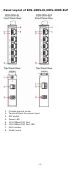
Panel Layout of EDS-2005-EL/EDS-2005-ELP 1. 2. 3. 4. 5. 6. 7. 8.
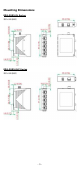
Mounting Dimensions EDS-2005-EL Series EDS-2005-ELP Series -5-
DIN-rail Mounting When shipped, the DIN-rail mounting kit is fixed to the back panel of the EDS. Mount the EDS on the corrosion-free mounting rail that adheres to the EN 60715 standard. Suggested Installation Method STEP 1: Insert the upper lip of the DINrail kit into the mounting rail. STEP 2: Press the device towards the mounting rail until it snaps into place. Alternatively, you can use a screwdriver to attach to the bottom of the DIN-rail kit and pull down.
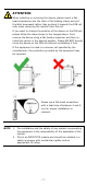
ATTENTION When installing or removing the device, please insert a flathead screwdriver into the latch of the holding clamp and pull the latch downward rather than pushing it towards the DIN rail side, when removing the module from the rail. If you want to change the position of the device on the DIN rail, please follow the steps shown in the images above. First, remove the device using a flat-head screwdriver and then reinstall the device in the desired position.
Wall Mounting (optional) For some applications, you will find it convenient to mount EDS on the wall, as illustrated below. There are two options for installation: The first option is to hook the EDS DIN-rail latch on the opening of the wall mount kit (see picture above) and then mount the wall-mount kit on the wall with screws. (The other option is to perform these two steps in the other order.) The heads of the screws should be less than 6.0 mm in diameter, and the shafts should be less than 3.
Wiring Requirements WARNING Do not disconnect modules or wires unless the power supply has been switched off or the area is known to be nonhazardous. The devices may only be connected to the supply voltage shown on the type plate. The devices are designed for operation with a Safety Extra-Low Voltage. Thus, they may only be connected to the supply voltage connections and to the signal contact with the Safety Extra-Low Voltages (SELV) in compliance with IEC950/ EN60950/ VDE0805.
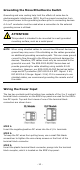
Grounding the Moxa EtherDevice Switch Grounding and wire routing help limit the effects of noise due to electromagnetic interference (EMI). Run the ground connection from the ground screw to the grounding surface prior to connecting devices. A 4 mm2 conductor must be used when a connection to the external grounding screw is utilized. ATTENTION This product is intended to be mounted to a well-grounded mounting surface, such as a metal panel.
NOTE The power source comes from secondary circuits. These circuits are separated from mains circuits by a transformer in which the primary windings are separated from the secondary windings by reinforced installation, double installation, or a screen connected to the protective conductor terminal. ATTENTION Before connecting the EDS to the DC power inputs, make sure the DC power source voltage is stable.
RJ45 (8-pin) to RJ45 (8-pin) Straight-through Cable Wiring RJ45 (8-pin) to RJ45 (8-pin) Cross-over Cable Wiring DIP Switch Settings DIP Switch Quality of Service (QoS) Setting Description Enable the Quality of Service to handle packet priorities in four WRR queues. ON OFF Broadcast Storm Protection (BSP) ON OFF QoS priority mapping matrix in each queue QoS 3bit priority 7, 6 5, 4 3, 2 1, 0 Queues 3 2 1 0 WRR 8 4 2 1 Disable the Quality of Service.
LED Indicators The front panel of the Moxa EtherDevice Switch contains several LED indicators. The function of each LED is described in the table below. LED Color State Description Power is being supplied to power input PWR. Power is not being supplied to power Off input PWR. When the port is active and links on On 100 Mbps. When the port’s data is being Blinking transmitted at 100 Mbps. Off When the port is inactive or link down. When the port is active and links on 10 On Mbps.
Switching and Address Learning The Moxa EDS has an address table that can hold up to 8,000 node addresses, which makes it suitable for use with large networks. The address tables are self-learning, so that as nodes are added or removed, or moved from one segment to another, EDS automatically keeps up with new node locations. An address-aging algorithm causes the least-used addresses to be deleted in favor of newer, more frequently used addresses.
Mechanical Casing IP40 protection, metal housing for EL Series; plastic housing for ELP Series Dimensions EDS-2005-EL: (W x H x D) 18 x 81 x 65 mm (0.7 x 3.19 x 2.56 in) EDS-2005-ELP: 19 x 81 x 65 mm (0.74 x 3.19 x 2.56 in) Weight EDS-2005-ELP: 56 g (0.12 lb) EDS-2005-EL: 105 g (0.23 lb) Installation DIN-rail, Wall Mounting (optional kit) Environmental Limits Note: For indoor use only.