EDS-2005-EL/ELP Series Quick Installation Guide Moxa EtherDevice Switch Version 1.0, October 2019 Technical Support Contact Information www.moxa.
Overview The EDS-2005-EL/ELP Series has a 5-port combination to simplify network expansion. There are two housing types available for the user to select depending on the requirements of their application. The ELP has a plastic housing and the EL has a metal housing. The compact switches provide a cost-effective solution for your industrial Ethernet connection requirements. The EDS-2005-EL/ELP Series provides 12/24/48 VDC (9.
Features High Performance Network Switching Technology • • • • 10/100BaseT(X) auto-negotiation speed, full/half duplex mode, auto MDI/MDI-X connection. IEEE 802.3 for 10BaseT, IEEE 802.3u for 100BaseT(X). IEEE 802.1p for Quality of Service (QoS) traffic prioritized function. Store-and-forward switching process type.
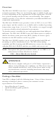
Panel Layout of EDS-2005-EL/EDS-2005-ELP 1. 2. 3. 4. 5. 6. 7. 8.
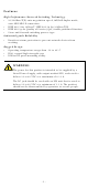
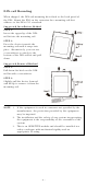
Mounting Dimensions EDS-2005-EL Series EDS-2005-ELP Series -5-
DIN-rail Mounting When shipped, the DIN-rail mounting kit is fixed to the back panel of the EDS. Mount the EDS on the corrosion-free mounting rail that adheres to the EN 60715 standard. Suggested Installation Method STEP 1: Insert the upper lip of the DINrail kit into the mounting rail. STEP 2: Press the device towards the mounting rail until it snaps into place. Alternatively, you can use a screwdriver to attach to the bottom of the DIN-rail kit and pull down.
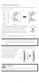
Wall Mounting (optional) For some applications, you will find it convenient to mount EDS on the wall, as illustrated below. There are two options for installation: The first option is to hook the EDS DIN-rail latch on the opening of the wall mount kit (see picture above) and then mount the wall-mount kit on the wall with screws. (The other option is to perform these two steps in the other order.) The heads of the screws should be less than 6.0 mm in diameter, and the shafts should be less than 3.
Wiring Requirements WARNING Do not disconnect modules or wires unless the power supply has been switched off or the area is known to be nonhazardous. The devices may only be connected to the supply voltage shown on the type plate. The devices are designed for operation with a Safety Extra-Low Voltage. Thus, they may only be connected to the supply voltage connections and to the signal contact with the Safety Extra-Low Voltages (SELV) in compliance with IEC950/ EN60950/ VDE0805.
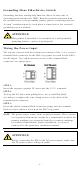
Grounding Moxa EtherDevice Switch Grounding and wire routing help limit the effects of noise due to electromagnetic interference (EMI). Run the ground connection from the ground screw to the grounding surface prior to connecting devices. A 4 mm2 conductor must be used when a connection to the external grounding screw is utilized. ATTENTION This product is intended to be mounted to a well-grounded mounting surface, such as a metal panel.
ATTENTION One individual conductor in a clamping point with 28-14 AWG wire size, and a torque value of 1.7 lb-in should be used. Communication Connections The EDS-2005-EL/ELP models have 10/100BaseT(X) Ethernet ports. 10/100BaseT(X) Ethernet Port Connection The 10/100BaseT(X) ports located on the EDS’s front panel are used to connect to Ethernet-enabled devices.
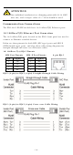
DIP Switch Settings DIP Switch Quality of Service (QoS) Setting ON Description Enable the Quality of Service to handle packet priorities in four WRR queues. QoS priority mapping matrix in each queue QoS 3bit 7, 6 5, 4 3, 2 1, 0 priority Queues 3 2 1 0 WRR 8 4 2 1 OFF ON Broadcast Storm Protection (BSP) OFF Disable the Quality of Service. Enables broadcast storm protection (at a maximum of 2048 broadcast packets per second) for each Ethernet port. Disables the broadcast storm protection.
Dual Speed Functionality and Switching The EDS’s 10/100 Mbps RJ45 switch port auto negotiates with the connected device for the fastest data transmission rate supported by both devices. The EDS is a plug-and-play device, so software configuration is not required at installation or during maintenance. The half/full duplex mode for the RJ45 switched ports is user dependent and changes (by auto-negotiation) to full or half duplex, depending on which transmission speed is supported by the attached device.
Specifications Technology Standards Flow Control Interface RJ45 Ports LED Indicators DIP Switch Switch Properties MAC Table Size Packet Buffer Size Processing Type Power Input Voltage Input Current (max.) Connection Overload Current Protection Reverse Polarity Protection Mechanical Casing IEEE 802.3 for 10BaseT, IEEE 802.3u for 100BaseT(X) and 100Base FX, IEEE 802.1p for Class of Service IEEE 802.
Shock Free Fall Vibration Warranty Address of Manufacturer IEC60068-2-27 IEC60068-2-32 IEC60068-2-6 5 years FL. 4, No.135, Lane 235, Baoqiao Road, Xindian District, New Taipei City, Taiwan R.O.C.