EDS-2008-EL/ELP Series Quick Installation Guide Moxa EtherDevice Switch Version 1.4, December 2022 Technical Support Contact Information www.moxa.com/support 2022 Moxa Inc. All rights reserved.
Overview The EDS-2008-EL/ELP Series has an 8-port combination to simplify network expansion. There are two housing types available for the user to select depending on the requirements of their application. The ELP has a plastic housing and the EL has a metal housing. The compact switches provide a cost-effective solution for your industrial Ethernet connection requirements. The EDS-2008-EL/ELP Series provides 12/24/48 VDC (9.
Features High-performance Network Switching Technology • • • • 10/100BaseT(X) auto-negotiation speed, full/half-duplex mode, auto MDI/MDI-X connection, and 100BaseFX for fiber port models. IEEE 802.3 for 10BaseT, IEEE 802.3u for 100BaseT(X). IEEE 802.1p for Quality of Service (QoS) traffic prioritized function. Store-and-forward switching process type.
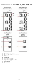
Panel Layout of EDS-2008-EL/EDS-2008-ELP 1. 2. 3. 4. 5. 6. 7. 8.
Panel Layout of EDS-2008-EL-M-ST/ EDS-2008-EL-M-SC 1. 2. 3. 4. 5. 6. 7. 8. 9. 10. 11.
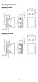
Mounting Dimensions EDS-2008-EL Series EDS-2008-ELP Series -6-
EDS-2008-EL-M-ST Series EDS-2008-EL-M-SC Series -7-
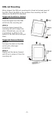
DIN-rail Mounting When shipped, the DIN-rail mounting kit is fixed to the back panel of the EDS. Mount the EDS on the corrosion-free mounting rail that adheres to the EN 60715 standard. Suggested Installation Method STEP 1: Insert the upper lip of the DINrail kit into the mounting rail. STEP 2: Press the device towards the mounting rail until it snaps into place. Alternatively, you can use a screwdriver to attach to the bottom of the DIN-rail kit and pull down.
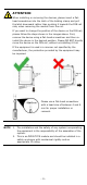
ATTENTION When installing or removing the devices, please insert a flathead screwdriver into the latch of the holding clamp and pull the latch downward rather than pushing it towards the DIN rail side, when removing the module from the rail. If you want to change the position of the device on the DIN rail, please follow the steps shown in the images above. First, remove the device using a flat-head screwdriver and then reinstall the device in the desired position.
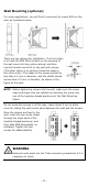
Wall Mounting (optional) For some applications, you will find it convenient to mount EDS on the wall, as illustrated below. There are two options for installation: The first option is to hook the EDS DIN-rail latch on the opening of the wall mount kit (see picture above) and then mount the wall-mount kit on the wall with screws. (The other option is to perform these two steps in the other order.) The heads of the screws should be less than 6.0 mm in diameter, and the shafts should be less than 3.
Wiring Requirements WARNING Do not disconnect modules or wires unless the power supply has been switched off or the area is known to be nonhazardous. The devices may only be connected to the supply voltage shown on the type plate. The devices are designed for operation with a Safety Extra-Low Voltage. Thus, they may only be connected to the supply voltage connections and to the signal contact with the Safety Extra-Low Voltages (SELV) in compliance with IEC950/ EN60950/ VDE0805.
ATTENTION This product is intended to be mounted to a well-grounded mounting surface, such as a metal panel. NOTE When using shielded cables to connect two Ethernet devices, a ground loop may occur if the shielding on the cables generates an additional grounding connection path. This can cause ground current to flow through to the Ethernet ports and damage the devices. Therefore, STP cables must only be connected to the ground at one end.
ATTENTION Before connecting the EDS to the DC power inputs, make sure the DC power source voltage is stable. ATTENTION One individual conductor in a clamping point with 28-14 AWG wire size, and a torque value of 1.7 lb-in should be used. ATTENTION The cable that is connected to the field wiring terminals must be capable of withstanding at least 105°C.. Communication Connections The EDS-2008-EL/ELP models have 10/100BaseT(X) Ethernet ports and 100BaseFX Ethernet ports.
RJ45 (8-pin) to RJ45 (8-pin) Cross-over Cable Wiring 100BaseFX Ethernet Port Connection The concept behind the SC/ST port and cable is quite straightforward. Suppose you are connecting devices I and II. As opposed to electrical signals, optical signals do not require a circuit in order to transmit data. Consequently, one of the optical lines is used to transmit data from device I to device II, and the other optical line is used transmit data from device II to device I, for full-duplex transmission.
DIP Switch Settings DIP Switch Quality of Service (QoS) Setting Description ON Enable the Quality of Service to handle packet priorities in four WRR queues. QoS priority mapping matrix in each queue QoS 3bit priority 7, 6 5, 4 3, 2 1, 0 Queues 3 2 1 0 WRR 8 4 2 1 Broadcast Storm Protection (BSP) OFF ON Disable the Quality of Service. Enables broadcast storm protection (at a maximum of 2048 broadcast packets per second) for each Ethernet port. Disables the broadcast storm protection.
Dual Speed Functionality and Switching The EDS’s 10/100 Mbps RJ45 switch port auto negotiates with the connected device for the fastest data transmission rate supported by both devices. The EDS is a plug-and-play device, so software configuration is not required at installation or during maintenance. The half/full duplex mode for the RJ45 switched ports is user dependent and changes (by auto-negotiation) to full or half duplex, depending on which transmission speed is supported by the attached device.
Specifications Technology Standards Flow Control Interface RJ45 Ports Fiber Ports LED Indicators DIP Switch Switch Properties MAC Table Size Packet Buffer Size Processing Type Power Input Voltage Input Current (max.) Connection Overload Current Protection Reverse Polarity Protection Mechanical Casing IEEE 802.3 for 10BaseT, IEEE 802.3u for 100BaseT(X) and 100Base FX, IEEE 802.1p for Class of Service IEEE 802.
EMS Shock Free Fall Vibration Warranty CISPR 35 (EN 55035) EN 61000-4-2 (ESD) EN 61000-4-3 (RS) EN 61000-4-4 (EFT) EN 61000-4-5 (Surge) EN 61000-4-6 (CS) EN 61000-4-8 (PFMF) IEC 60068-2-27 IEC 60068-2-32 IEC 60068-2-6 5 years - 18 -