
Installation Guide
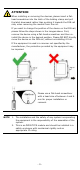
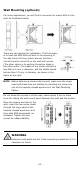

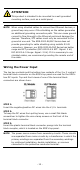
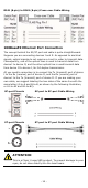
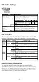

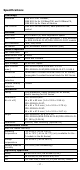
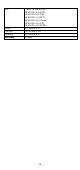
Table Of Contents
- EDS-2008-EL/ELP Series Quick Installation Guide
- Overview
- Package Checklist
- Features
- Panel Layout of EDS-2008-EL/EDS-2008-ELP
- Panel Layout of EDS-2008-EL-M-ST/EDS-2008-EL-M-SC
- Mounting Dimensions
- DIN-rail Mounting
- Wall Mounting (optional)
- Wiring Requirements
- Grounding the Moxa EtherDevice Switch
- Wiring the Power Input
- Communication Connections
- 100BaseFX Ethernet Port Connection
- DIP Switch Settings
- LED Indicators
- Auto MDI/MDI-X Connection
- Dual Speed Functionality and Switching
- Switching, Filtering, and Forwarding
- Switching and Address Learning
- Auto-negotiation and Speed Sensing
- Specifications

- 12 -
ATTENTION
This product is intended to be mounted to a well
-grounded
mounting surface, such as a metal panel.
NOTE
When using shielded cables to connect two Ethernet devices, a
ground loop may occur if the shielding on the cables generates
an additional grounding connection path. This can cause ground
current to flow through to the Ethernet ports and damage the
devices. Therefore, STP cables must only be connected to t
he
ground at one end. The EDS
-2000-EL/ELP Series does not
provide grounding for cable shielding using metallic RJ
-45
connectors. However, our EDS
-2000-EL/ELP Series has better
surge and EFT protection (IEC 61000
-4-4 EFT: Signal: 2 kV,
IEC 61000
-4-5 Surge: Signal: 2 kV). If it is necessary to use
shielded cables, we recommend grounding the remote end of
the cable.
Wiring the Power Input
The top two contacts and the bottom two contacts of the 2 or 3 contact
terminal block connector on the EDS’s top panel are used for the EDS’s
two DC inputs. Top and front views of one of the terminal block
connectors are shown here.
STEP 1:
Insert the negative/positive DC wires into the V-/V+ terminals.
STEP 2:
To keep the DC wires from pulling loose, use a small flat-blade
screwdriver to tighten the wire-clamp screws on the front of the
terminal block connector.
STEP 3:
Insert the plastic terminal block connector prongs into the terminal
block receptor, which is located on the EDS’s top panel.
NOTE
The power source comes from secondary circuits. These circuits
are separated from mains circuits by a transformer in which the
primary windings are separated from the secondary windings
by reinforced installation, double installation, or a screen
connected to the protective conductor terminal.