
Installation Guide
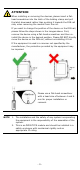
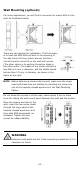

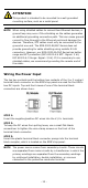
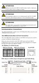
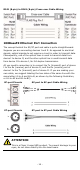
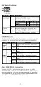

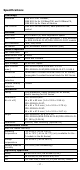
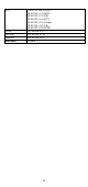
Table Of Contents
- EDS-2008-EL/ELP Series Quick Installation Guide
- Overview
- Package Checklist
- Features
- Panel Layout of EDS-2008-EL/EDS-2008-ELP
- Panel Layout of EDS-2008-EL-M-ST/EDS-2008-EL-M-SC
- Mounting Dimensions
- DIN-rail Mounting
- Wall Mounting (optional)
- Wiring Requirements
- Grounding the Moxa EtherDevice Switch
- Wiring the Power Input
- Communication Connections
- 100BaseFX Ethernet Port Connection
- DIP Switch Settings
- LED Indicators
- Auto MDI/MDI-X Connection
- Dual Speed Functionality and Switching
- Switching, Filtering, and Forwarding
- Switching and Address Learning
- Auto-negotiation and Speed Sensing
- Specifications

- 13 -
ATTENTION
Before connecting
the EDS to the DC power inputs, make sure
the DC power source voltage is stable.
ATTENTION
One individual
conductor in a clamping point with 28-14 AWG
wire size, and a torque value of 1.7 lb-in should be used.
ATTENTION
The
cable that is connected to the field wiring terminals must
be capable of withstanding at least 105°C..
Communication Connections
The EDS-2008-EL/ELP models have 10/100BaseT(X) Ethernet ports and
100BaseFX Ethernet ports.
10/100BaseT(X) Ethernet Port Connection
The 10/100BaseT(X) ports located on the EDS’s front panel are used to
connect to Ethernet-enabled devices.
Below we show pinouts for both MDI (NIC-type) ports and MDI-X
(HUB/Switch-type) ports, and show cable wiring diagrams for straight-
through and cross-over Ethernet cables.
10/100Base T(x) RJ45 Pinouts
MDI Port Pinouts
MDI-X Port Pinouts
8-pin RJ45
Pin
Signal
1
Tx+
2
Tx-
3
Rx+
6
Rx-
Pin
Signal
1
Rx+
2
Rx-
3
Tx+
6
Tx-
RJ45 (8-pin) to RJ45 (8-pin) Straight-through Cable Wiring