
Installation Guide
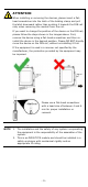
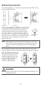

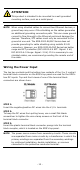
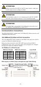
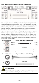
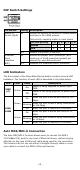

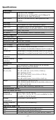

Table Of Contents
- EDS-2008-EL/ELP Series Quick Installation Guide
- Overview
- Package Checklist
- Features
- Panel Layout of EDS-2008-EL/EDS-2008-ELP
- Panel Layout of EDS-2008-EL-M-ST/EDS-2008-EL-M-SC
- Mounting Dimensions
- DIN-rail Mounting
- Wall Mounting (optional)
- Wiring Requirements
- Grounding the Moxa EtherDevice Switch
- Wiring the Power Input
- Communication Connections
- 100BaseFX Ethernet Port Connection
- DIP Switch Settings
- LED Indicators
- Auto MDI/MDI-X Connection
- Dual Speed Functionality and Switching
- Switching, Filtering, and Forwarding
- Switching and Address Learning
- Auto-negotiation and Speed Sensing
- Specifications

- 14 -
RJ45 (8-pin) to RJ45 (8-pin) Cross-over Cable Wiring
100BaseFX Ethernet Port Connection
The concept behind the SC/ST port and cable is quite straightforward.
Suppose you are connecting devices I and II. As opposed to electrical
signals, optical signals do not require a circuit in order to transmit data.
Consequently, one of the optical lines is used to transmit data from
device I to device II, and the other optical line is used transmit data
from device II to device I, for full-duplex transmission.
All you need to remember is to connect the Tx (transmit) port of device
I to the Rx (receive) port of device II, and the Rx (receive) port of
device I to the Tx (transmit) port of device II. If you are making your
own cable, we suggest labeling the two sides of the same line with the
same letter (A-to-A and B-to-B, as shown by the following illustration,
or A1-to-A2 and B1-to-B2).
SC-port Pinouts
SC-port to SC-port Cable Wiring
ST-port Pinouts
ST-port to ST-port Cable Wiring
ATTENTION
This is a Class 1 Laser/LED product. To prevent damage to your
eyes, do not stare directly into the laser beam.