EDS-205A/208A Series Quick Installation Guide Moxa EtherDevice Switch Edition 8.2, October 2018 Technical Support Contact Information www.moxa.
Overview The EDS-205A/208A series of industrial Ethernet switches are entrylevel industrial 5 and 8-port Ethernet switches that support IEEE 802.3, IEEE 802.3u, and IEEE 802.3x with 10/100M, full/half-duplex, and MDI/MDIX auto-sensing. The EDS-205A/208A series provides 12/24/48 VDC (9.6 to 60 VDC) redundant power inputs.
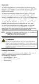
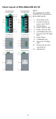
Panel Layout of EDS-205A/208A (Standard) 1. 2. 3. 4. 5. 6. 7. 8. 9. 10. 11.
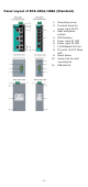
Panel Layout of EDS-205A-M-SC/ST NOTE: The appearance of EDS205A-S-SC is identical to EDS-205A-M-SC. 1. 2. 3. 4. 5. 6. 7. 8. 9. 10. 11. 12. 13.
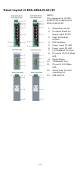
Panel Layout of EDS-208A-M-SC/ST NOTE: The appearance of EDS208A-S-SC is identical to EDS-208A-M-SC. 1. 2. 3. 4. 5. 6. 7. 8. 9. 10. 11. 12.
Panel Layout of EDS-208A-MM-SC/ST NOTE: The appearance of EDS208A-SS-SC is identical to EDS-208A-MM-SC. 1. 2. 3. 4. 5. 6. 7. 8. 9. 10. 11. 12.
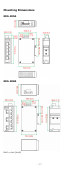
Mounting Dimensions EDS-205A EDS-208A Unit = mm (inch) -7-
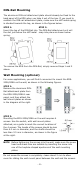
DIN-Rail Mounting The aluminum DIN-rail attachment plate should already be fixed to the back panel of the EDS when you take it out of the box. If you need to reattach the DIN-rail attachment plate, make sure the stiff metal spring is situated towards the top, as shown in the figures below. STEP 1: STEP 2: Insert the top of the DIN-Rail into The DIN-Rail attachment unit will the slot just below the stiff metal snap into place as shown below. spring.
STEP 3: Once the screws are fixed on the wall, insert the four screw heads through the large parts of the keyhole-shaped apertures, and then slide the EDS-205A/208A downwards, as indicated. Tighten the four screws for added stability. ATEX and IECEx Information 1. 2. 3. 4. 5. Certificate number ATEX: DEMKO 10 ATEX 0909900X IECEx: IECEx UL 14.
WARNING EXPLOSION HAZARD - Substitution of any component may impair suitability for Class 1, Division 2 Wiring Requirements WARNING Safety First! Turn the power off before disconnecting modules or wires. The correct power supply voltage is listed on the product label. Check the voltage of your power source to make sure that you are using the correct voltage. Do NOT use a voltage greater than what is specified on the product label.
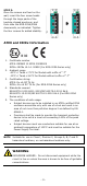
Wiring the Redundant Power Inputs The top two contacts and the bottom two contacts of the 4-contact terminal block connector on the EDS’s top panel are used for the EDS’s two DC inputs. Top and front views of one of the terminal block connectors are shown here. STEP 1: Insert the negative/positive DC wires into the V-/V+ terminals. STEP 2: To keep the DC wires from pulling loose, use a small flat-blade screwdriver to tighten the wire-clamp screws on the front of the terminal block connector.
10/100Base T(x) RJ45 Pinouts MDI Port Pinouts Pin Signal 1 Tx+ 2 Tx3 Rx+ 6 Rx- MDI-X Port Pinouts Pin Signal 1 Rx+ 2 Rx3 Tx+ 6 Tx- 8-pin RJ45 RJ45 (8-pin) to RJ45 (8-pin) Straight-Through Cable Wiring RJ45 (8-pin) to RJ45 (8-pin) Cross-Over Cable Wiring 100BaseFX Ethernet Port Connection The concept behind the SC/ST port and cable is quite straightforward. Suppose you are connecting devices I and II; contrary to electrical signals, optical signals do not require a circuit in order to transmit data.
ST-Port Pinouts ST-Port to ST-Port Cable Wiring ATTENTION This is a Class 1 Laser/LED product. To avoid causing serious damage to your eyes, do not stare directly into the Laser Beam. Redundant Power Inputs Both power inputs can be connected simultaneously to live DC power sources. If one power source fails, the other live source acts as a backup, and automatically supplies all of the EDS’s power needs. DIP Switch Settings EDS-205A/208A DIP Switches The default setting for each DIP Switch is OFF.
Blinking Data is being transmitted at 100 Mbps. Off 100Base TP/FX Port’s link is inactive. Auto MDI/MDI-X Connection The Auto MDI/MDI-X function allows users to connect the EDS’s 10/100BaseTX ports to any kind of Ethernet device, without needing to pay attention to the type of Ethernet cable being used for the connection. This means that you can use either a straight-through cable or cross-over cable to connect the EDS to Ethernet devices.
100 Mbps transmission speeds, with the device at the other end of the cable expected to advertise in a similar manner. Depending on what type of device is connected, this will result in agreement to operate at a speed of either 10 Mbps or 100 Mbps. If an EDS RJ45 Ethernet port is connected to a non-negotiating device, it will default to 10 Mbps speed and half-duplex mode, as required by the IEEE 802.3u standard.
0.11 A (EDS-208A-S) 0.14 A (EDS-208A-MM) 0.15 A (EDS-208A-SS) Rated Supply Voltage and 12/24/48 V DC. Maximum 0.25 A, Class2 Current (For EDS-205A Series only) Connection Removable 4-contact terminal block Inrush current EDS-205A: Max. 6.24A @ 24VDC (0.1 1ms) EDS-208A: Max. 8.81A @ 24VDC (0.
WARNING This equipment is intended to be used in a Restricted Access Location. WARNING: HOT SURFACE!! Before touching it, special attention or protection is required.