
User Manual


- 11 -
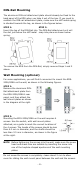
Wiring the Redundant Power Inputs
The top two contacts and the bottom two contacts of the 4-contact
terminal block connector on the EDS’s top panel are used for the EDS’s
two DC inputs. Top and front views of one of the terminal block
connectors are shown here.
STEP 1:
Insert the negative/positive
DC wires into the V-/V+
terminals.
STEP 2:
To keep th
e DC wires from pulling loose, use a small
flat
-blade screwdriver to tighten the wire-clamp
screws on the front of the terminal block connector.
STEP 3:
Insert the plastic terminal block connector prongs
into the terminal block receptor, which is located
on
EDS’s top panel.
ATTENTION
Before connecting the EtherDevice Switch to the
DC power
inputs, make sure the DC power source voltage is stable.
NOTE
For use in Pollution Degree 2 Environment” or similar
environment.
Field Wiring Terminal Markings
– Wiring terminals shall be
marked to indicate the proper connections for power supply and
load, or a wiring diagram coded to the terminal marking shall
be securely attached to the device, and “Use Copper
Conductors Only, Tig
hten to 4.5 pound-inches” or equivalent.
This marking should be located adjacent to the terminal or on
the wiring diagram.
Communication Connections
The EDS-205A models have 4 or 5 10/100BaseT(X) Ethernet ports, and
1 or 0 (zero) 100 BaseFX multi/single-mode (SC/ST-type connector)
fiber ports. The EDS-208A models have 6, 7 or 8 10/100BaseT(X)
Ethernet ports, and 2, 1 or 0 (zero) 100 BaseFX multi/single-mode
(SC/ST-type connector) fiber ports.
10/100BaseT(X) Ethernet Port Connection
The 10/100BaseT(X) ports located on the EDS’s front panel are used to
connect to Ethernet-enabled devices. Below we show pinouts for both
MDI (NIC-type) ports and MDI-X (HUB/Switch-type) ports, and also
show cable wiring diagrams for straight-through and cross-over
Ethernet cables.