ED S- 4 0 0 8 Se r ie s Quick I nst a lla t ion Guide M ox a Et he r D e vice ™ Sw it ch Ve r sion 1 .0 , M a r ch 2 0 2 2 Te chnica l Suppor t Con t a ct I nfor m a t ion w w w .m ox a . com / suppor t 2022 Moxa I nc. All right s reserv ed.
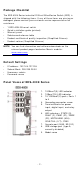
Pa ck a ge Che ck list The EDS- 4008 Series indust rial DI N- rail Et herDevice Sw it ch ( EDS) is shipped w it h t he follow ing it em s. I f any of t hese it em s are m issing or dam aged, please cont act y our cust om er service represent at ive for assist ance.
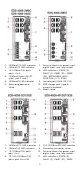
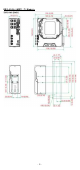
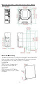
1. 2. 3. 4. 5. 6. 100BaseT( X) LED indicat or 10BaseT( X) LED indicat or 10/ 100BaseT( X) port s, port s 3 t o 8 100BaseFX port ( SC/ ST t ype) , port 1 and 2 100BaseFX LED indicat or Grounding connect or screw 7. 8. 9. 10. 11. 1. 2. 3. 4. 100BaseT( X) LED indicat or 10BaseT( X) LED indicat or 10/ 100BaseT( X) port s, port 1 t o 4 10/ 100/ 1000BaseT( X) port s, port G3 t o G4 8. 9. 10. 11.
5. 6. 7. 1000BaseT( X) LED indicat or 10/ 100BaseT( X) LED indicat or 100/ 1000BaseSFP port s, port G1 t o G2 12. 13. 14. 15. ( P2) , MSTR/ HEAD ( M/ H) , CPLR/ TAI L ( C/ T) , SYNC Console port ( RJ45, RS- 232) USB st orage port ( t ype A, current ly disabled) Model nam e Sm art PoE LED indicat or of PoE port s Bot t om Pa ne l Vie w 1. 2. 3.
ED S- 4 0 0 8 - 2 M ST( - T) M ode ls - 5 -
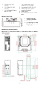
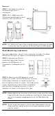
ED S- 4 0 0 8 - 2 GT- 2 GS( - T) / ED S- 4 0 0 8 - 4 P- 2 GT- 2 GS( - T) M ode ls D I N - r a il M ount ing The DI N- rail m ount ing k it is fixed t o t he back panel of t he EDS device w hen you t ake it out of t he box. Mount t he EDS device on corrosionfree m ount ing rails t hat m eet t he EN 60715 st andard. I nst a lla t ion STEP 1 —I nsert t he upper lip of t he DI N rail int o t he DI N- rail m ount ing kit . STEP 2 —Press t he EDS device t ow ards t he DI N rail unt il it snaps int o place.
Re m ova l STEP 1 —Pull dow n t he lat ch on t he m ount ing kit w it h a screw driver. STEP 2 & 3 —Slight ly pull t he EDS device forw ard and lift up t o rem ove it from t he DI N rail. N OTE Our DI N rail kit now ut ilizes a quick release m echanism t o m ake it easier for user s t o rem ove t he DI N rail from t he EDS device.
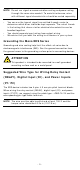
STEP 3 —Once t he screw s are fixed t o t he w all, insert t he four screw heads t hrough t he w ide part s of t he keyholeshaped apert ures, and t hen slide t he EDS device dow nw ards, as indicat ed in t he figure at t he right . Tight en t he four screw s for m ore st abilit y. W ir ing Re quir e m e nt s ATTEN TI ON Sa fe t y Fir st ! Ext ernal m et al part s are hot . Take t he necessar y precaut ions if you are required t o handle t he device.
N OTE • • • Do not run signal or com m unicat ions w iring and pow er w iring t hrough t he sam e w ire conduit . To avoid int erference, w ires w it h different signal charact erist ics should be rout ed separat ely. You can use t he t ype of signal t ransm it t ed t hrough a w ire t o det erm ine w hich w ires should be k ept separat e. The rule of t hum b is t hat w iring t hat shares sim ilar elect rical charact erist ics can be bundled t oget her.
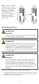
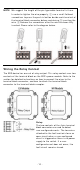
N OTE We suggest t he lengt h of t he pin t ype cable t er m inal is 8 m m . I n order t o t ight en t he w ire proper ly, ① use a sm all flat head screw driver t o press t he push - in but t on beside each t er m inal of t he t erm inal block connect or befor e and during ② insert ing t he w ire. ③ Release t he screw driver aft er t he w ire has been fully insert ed. Please refer t o t he diagram below . W ir ing t he Re la y Cont a ct The EDS device has one set of relay out put .
W ir ing t he Re dunda nt Pow e r I n put s The EDS device includes bot h high- volt age and low - volt age pr oduct s. For t he low - volt age ( LV m odels) product s, t here are t w o pow er input s for redundancy ; for t he high - volt age ( HV m odels) pr oduct s, t here is only one pow er input . Refer t o t he inst ruct ions and diagram below on how t o connect t he w ires t o t he t erm inal block connect or on t he recept or.
STEP 1 : I nsert t he negat ive ( ground) / posit ive DI w ires int o t he ┴/ I t erm inals, respect ively. STEP 2 : To keep t he DI w ires from pulling loose, use a sm all flat - blade screw driver t o t ight en t he w ire- clam p but t on on t he front of t he t erm inal block connect or. STEP 3 : I nsert t he plast ic t erm inal block connect or prongs int o t he t erm inal block recept or, w hich is locat ed on t he EDS devices’ right side.
RJ4 5 Console Por t Pinou t s Pin 1 2 3 4 5 6 7 8 D e scr ipt ion DSR RTS – TxD RxD GND CTS DTR USB Conn e ct ion N OTE The USB funct ion is current ly reserved and m ay be required in t he fut ure. I t should be not ed t hat t his port cannot be used for charging any devices. 1 0 / 1 0 0 Ba se T( X) Et h e r n e t Por t Con n e ct ion The 10/ 100BaseT( X) port s locat ed on t he front panel of t he sw it ch are used t o connect t o Et hernet - enabled devices.
RJ4 5 ( 8 - pin) t o RJ4 5 ( 8 - pin) Cr oss- Ove r Ca ble W ir ing 1 0 0 Ba se Fx Et h e rn e t Por t Con n e ct ion The concept behind t he SC/ ST por t and cable is quit e st raight forw ar d. Suppose you are connect ing devices I and I I . As opposed t o elect rical signals, opt ical signals do not require a circuit in order t o t ransm it dat a.
1 0 0 0 Ba se T( X) Et h e r n et Por t Conn e ct ion 1000BaseT( X) dat a is t ransm it t ed on different ial TRD+ / - signal pair s over copper w ires.
Re se t But t on There are t w o funct ions available on t he Reset But t on. One is t o reset t he Et hernet sw it ch t o fact ory default set t ings by pressing and holding t he Reset but t on for 5 seconds. Use a point ed obj ect , such as a st raight ened paper clip or t oot hpick, t o depress t he Reset but t on. This w ill cause t he STATE LED t o blink once a second. Aft er depressing t he but t on for 5 cont inuous seconds, t he STATE LED w ill st art t o blink rapidly.
N OTE You m ust enable t he Tur bo Ring ( DI P sw it ch 5) fir st before using t he DI P sw it ch t o act ivat e t he Mast er and Coupler funct ions. N OTE I f y ou do not enable any of t he EDS sw it ches t o be t he Ring Mast er, t he Turbo Ring prot ocol w ill aut om at ically choose t he EDS sw it ch w it h t he sm allest MAC address range t o be t he Ring Mast er.
LED Color M STR/ H EAD ( M/ H) Gr e e n CPLR/ TAI L Gr e e n Syst e m LED ( Ex ce pt PW R) Syst e m LED ( Ex ce pt PW R) St a t e D e scr ipt ion When t he sw it ch is On Mast er/ Head/ Root of Tur bo Ring/ Turbo Chain/ Fast RSTP. 1. The sw it ch has becom e t he Mast er of Turbo Ring aft er Turbo Ring has gone dow n 2. The sw it ch is set as Head of Turbo Chain and Turbo Chain has gone dow n 3.
Sm a r t PoE LED I ndica t or s LED Color St a t e D e scr ipt ion When t he port is connect ed t o I EEE 802.3bt pow ered device and pow ered at : • Single signat ure ( PD) Class On 5 to 8 • Dual signat ure ( PD) Class 1 to 5 Gr e e n 1. When t he pow er is not being supplied t o a pow ered device ( PD) Off 2. The port is not connect ed t o an I EEE 802.3bt pow ered device When t he port is connect ed t o I EEE 802.
LED t op LED 1 0 M/ 1 0 0 M/ 1000M Coppe r bot t om LED Color St a t e Off On Am be r Blink ing ( 4 t im e s/ se c) Off On 100M Fibe r LED Gr e e n Blink ing ( 4 t im e s/ se c) Off On Gr e e n 1 0 0 M/ 1000M ( SFP por t ) Blink ing ( 4 t im e s/ se c) Off On Am be r Blink ing ( 4 t im e s/ se c) Off D e scr ipt ion When t he port is inact ive or link dow n. When t he port is act ive and link s at 10/ 100Mbps. When t he port ’s dat a is being t ransm it t ed at 10/ 100Mbps.
PoE Out put Pow er 15.4 W for t he 802.3af st andard, 30 W for t he 802.3at st andard, 36 W in high pow er m ode, 60 W in 802.3bt st andard PoE Out put Current 350 m A for t he 802.3af st andard, 600 m A for t he 802.3at st andard, 1960 m A for t he 802.
I nrush Current EDS- 4008- 2GT- 2GS- LV( - T) m odels: 9.41 W EDS- 4008- 2GT- 2GS- HV( - T) m odels: 11.17 W EDS- 4008- 4P- 2GT- 2GS- LVA( - T) m odels: Wit hout PoE: 11.22 W Wit h PoE: Max. 240 W for t ot al PD pow er consum pt ion @ 48 VDC input EDS- 4008- 4P- 2GT- 2GS- LVB( - T) m odels: Wit hout PoE: 15.84 W Wit h PoE: Max. 180 W for t ot al PD pow er consum pt ion @ 48 VDC input ; Max. 150 W for t ot al PD pow er consum pt ion @ 24 VDC input ; Max.
EMS Shock Free Fall Vibrat ion Rail Traffic ( Wayside) Traffic Cont rol W arranty Warrant y EN 61000- 4- 2 ( ESD) Level 4 EN 61000- 4- 3 ( RS) Level 3 EN 61000- 4- 4 ( EFT) Level 4 EN 61000- 4- 5 ( Surge) Level 4 EN 61000- 4- 6 ( CS) Level 3 EN 61000- 4- 8 Level 4 I EC 60068- 2- 27 I EC 60068- 2- 32 I EC 60068- 2- 6 EN 50121- 4 NEMA TS2 5 years ATTEN TI ON This device com plies w it h Part 15 of t he FCC rules. Operat ion is subj ect t o t he follow ing condit ions: 1.