
Installation Guide
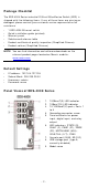
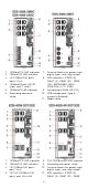
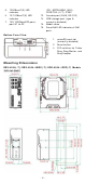
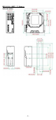
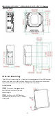
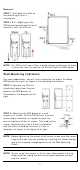
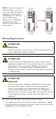
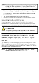
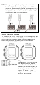
Table Of Contents
- EDS-4008 Series Quick Installation Guide
- Package Checklist
- Default Settings
- Panel Views of EDS-4008 Series
- Mounting Dimensions
- DIN-rail Mounting
- Wall Mounting (Optional)
- Wiring Requirements
- Grounding the Moxa EDS Series
- Suggested Wire Type for Wiring Relay Contact (RELAY), Digital Input (DI), and Power Inputs (P1/P2)
- Wiring the Relay Contact
- Wiring the Redundant Power Inputs
- Wiring the Digital Inputs
- Rotating the Power Module
- Communication Connections
- Reset Button
- Turbo Ring DIP Switch Settings
- LED Indicators
- Specifications

- 3 -
1. 100BaseT( X) LED indicat or
2. 10BaseT( X) LED indicat or
3. 10/ 100BaseT( X) por t s,
port s 3 t o 8
4. 100BaseFX por t ( SC/ ST
t ype) , port 1 and 2
5. 100BaseFX LED in dicat or
6. Grounding connect or
screw
7. Ter m inal blocks for pow er input ,
digital input , and relay out put
8. LED indicator s: STATE ( S) ,
FAULT ( F), PWR1 ( P1) , PWR2
( P2), MSTR/ HEAD (M/ H),
CPLR/ TAI L ( C/ T) , SYNC
9. Console por t ( RJ45, RS- 232)
10.
USB st orage port ( t ype A,
current ly disabled)
11. Model nam e
1. 100BaseT( X) LED indicat or
2. 10BaseT( X) LED indicat or
3. 10/ 100BaseT( X) por t s,
por t 1 t o 4
4. 10/ 100/ 1000BaseT( X)
por ts, por t G3 t o G4
8. 100/ 1000BaseSFP LED indicat or
9. Grounding connect or screw
10.
Ter m inal block s for power in put,
digital input , and relay out put
11.
LED indicator s: STATE ( S) ,
FAULT ( F), PWR1 ( P1) , PWR2