
Installation Guide
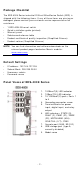
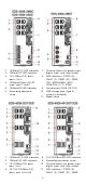
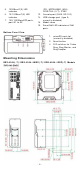
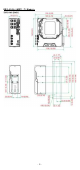
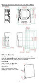
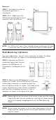
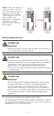
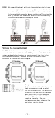
Table Of Contents
- EDS-4008 Series Quick Installation Guide
- Package Checklist
- Default Settings
- Panel Views of EDS-4008 Series
- Mounting Dimensions
- DIN-rail Mounting
- Wall Mounting (Optional)
- Wiring Requirements
- Grounding the Moxa EDS Series
- Suggested Wire Type for Wiring Relay Contact (RELAY), Digital Input (DI), and Power Inputs (P1/P2)
- Wiring the Relay Contact
- Wiring the Redundant Power Inputs
- Wiring the Digital Inputs
- Rotating the Power Module
- Communication Connections
- Reset Button
- Turbo Ring DIP Switch Settings
- LED Indicators
- Specifications

- 4 -
5. 1000BaseT( X) LED
indicator
6. 10/ 100BaseT( X) LED
indicator
7. 100/ 1000BaseSFP por ts,
port G1 t o G2
( P2), MSTR/ HEAD (M/ H),
CPLR/ TAI L ( C/ T) , SYNC
12.
Console por t ( RJ45, RS- 232)
13.
USB st or age port ( t y pe A,
cur rent ly disabled)
14.
Model nam e
15.
Sm ar tPoE LED in dicat or of PoE
port s
Bot t om Pa ne l Vie w
1. m icroSD car d slot
(curr ent ly disabled)
2. Reset but t on
3.
DI P sw itches for Turbo
Ring, Ring Mast er, and
Ring Coupler
M ount ing D im en sions
ED S- 4 0 0 8 ( - T) / ED S- 4 0 0 8 - 2 M SC( - T) / ED S- 4 0 0 8 - 2 SSC( - T) Mode ls