
Installation Guide
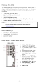
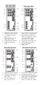
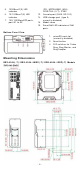
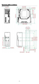
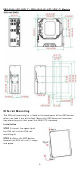
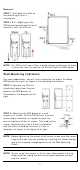
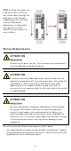
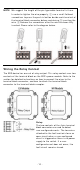
Table Of Contents
- EDS-4008 Series Quick Installation Guide
- Package Checklist
- Default Settings
- Panel Views of EDS-4008 Series
- Mounting Dimensions
- DIN-rail Mounting
- Wall Mounting (Optional)
- Wiring Requirements
- Grounding the Moxa EDS Series
- Suggested Wire Type for Wiring Relay Contact (RELAY), Digital Input (DI), and Power Inputs (P1/P2)
- Wiring the Relay Contact
- Wiring the Redundant Power Inputs
- Wiring the Digital Inputs
- Rotating the Power Module
- Communication Connections
- Reset Button
- Turbo Ring DIP Switch Settings
- LED Indicators
- Specifications

- 6 -
ED S- 4 0 0 8 - 2 GT- 2 GS( - T) / ED S- 4 0 0 8 - 4 P- 2 GT- 2 GS( - T) M ode ls
DI N - r a il M ou nt ing
The DI N- rail m ount ing k it is fixed to t he back panel of t he EDS device
when you t ake it out of t he box. Mount t he EDS device on cor rosion -
fr ee m ount ing rails that m eet t he EN 60715 stan dar d.
I nst allat ion
STEP 1 —I nser t t he upper lip of
the DI N r
ail int o t he DI N- rail
m ounting kit.
STEP 2
—Press t he EDS device
towar ds t he
DI N rail
until it snaps
int o place.