
Installation Guide
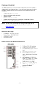
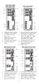
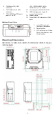
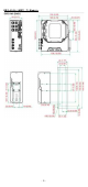
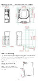
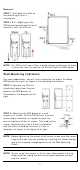
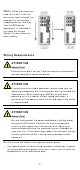
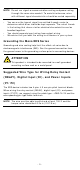
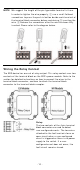
Table Of Contents
- EDS-4008 Series Quick Installation Guide
- Package Checklist
- Default Settings
- Panel Views of EDS-4008 Series
- Mounting Dimensions
- DIN-rail Mounting
- Wall Mounting (Optional)
- Wiring Requirements
- Grounding the Moxa EDS Series
- Suggested Wire Type for Wiring Relay Contact (RELAY), Digital Input (DI), and Power Inputs (P1/P2)
- Wiring the Relay Contact
- Wiring the Redundant Power Inputs
- Wiring the Digital Inputs
- Rotating the Power Module
- Communication Connections
- Reset Button
- Turbo Ring DIP Switch Settings
- LED Indicators
- Specifications

- 7 -
Re m ov al
STEP 1
—Pull down t he lat ch on
the m ount ing kit w it h a
scr ew dr iver.
STEP 2
& 3 —Slightly pull the
EDS device for war d and lift up t o
rem ove it from t he DI N rail.
N OTE
Our DI N rai
l kit now
utilizes a quick release m echanism to m ake
it easier for user s t o rem ove the DI N rail from t he EDS device.
W a ll Mount ing ( Opt iona l)
For som e applications, y ou will fin d it convenient to m ount t he Moxa
EDS device on a w all, as show n in the following illust rations:
STEP 1 —
Rem ove t he DI N- rail
at tachm ent pl
at e fr om t he rear
panel of t he EDS device,
as
illust rat ed
in the diagram on t he
right
.
STEP 2 —
Mount ing t he EDS device on a w all
requires
six screws. Use t he EDS device, with w all
m ount plat es at t ached, as a guide t o m ark t he
cor rect locat ions of t he
six scr ew s. T
he heads of t he
screws sh ould be less t han 6.0 m m in diam et er ,
and t he shaft s should be less t han 3.5
m m in
diam et er, as sh own in t he figure on at r ight .
N OTE
Befor e t ightening t he screws int o t he wall, m ake sure t he scr ew
head and shank size are suit able by insert ing t he screw t hrough
one of the keyhole
-shaped apert ures of t he Wall Mount ing
Plates.
N OTE
Do not scr ew t he screw s in all t he w ay
—leave about 2 m m t o
allow room for sliding t he wall m ount panel between t he wall
and t he scr ew s.