ED S- 4 0 1 4 Se r ie s Quick I nst a lla t ion Guide M ox a Et he r D e vice ™ Sw it ch Ve r sion 1 .0 , M a r ch 2 0 2 2 Te chnica l Suppor t Con t a ct I nfor m a t ion w w w .m ox a . com / suppor t 2022 Moxa I nc. All right s reserv ed.
Pa ck a ge Che ck list The EDS- 4014 Series indust rial DI N- rail Et herDevice Sw it ch ( EDS) is shipped w it h t he follow ing it em s. I f any of t hese it em s are m issing or dam aged, please cont act y our cust om er service represent at ive for assist ance.
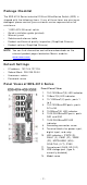
Bot t om Pa ne l Vie w 1. 2. 3.
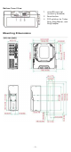
D I N - r a il M ount ing The DI N- rail m ount ing k it is fixed t o t he back panel of t he EDS device w hen you t ake it out of t he box. Mount t he EDS device on corrosionfree m ount ing rails t hat m eet t he EN 60715 st andard. I nst a lla t ion STEP 1 —I nsert t he upper lip of t he DI N rail int o t he DI N- rail m ount ing kit . STEP 2 —Press t he EDS device t ow ards t he DI N rail unt il it snaps int o place. Re m ova l STEP 1 —Pull dow n t he lat ch on t he m ount ing kit w it h a screw driver.
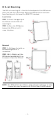
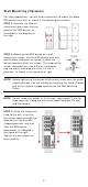
W a ll M ount ing ( Opt iona l) For som e applicat ions, y ou w ill find it convenient t o m ount t he Moxa EDS device on a w all, as show n in t he follow ing illust rat ions: STEP 1 —Rem ove t he DI N rail at t achm ent plat e fr om t he rear panel of t he EDS device, as illust rat ed in t he diagram on t he right . STEP 2 —Mount ing t he EDS device on a w all requires six screw s.
W ir ing Re quir e m e nt s ATTEN TI ON Sa fe t y Fir st ! Ext ernal m et al part s are hot . Take t he necessar y precaut ions if you are required t o handle t he device. ATTEN TI ON I n order t o ensure reliable operat ions, please m ake sure t he operat ing t em perat ure of t he environm ent does not exceed t he specificat ions.
Gr oun ding t he M ox a ED S Se r ie s Grounding and w ire r out ing help lim it t he effect s of noise due t o elect rom agnet ic int erference ( EMI ) . Run t he ground connect ion from t he ground screw t o t he grounding surface prior t o connect ing devices. ATTEN TI ON This product is int ended t o be m ount ed t o a w ell- gr ounded m ount ing surface such as a m et al panel.
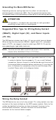
Re la y: The t w o cont act s of t he 4- pin t erm inal block connect or are used t o det ect user- configured event s. The t w o w ires at t ached t o t he fault cont act s for m an open cir cuit w hen a user- configured event is t riggered or t here is no pow er supply t o t he sw it ch. I f a userconfigured event does not occur, t he fault cir cuit rem ains closed. W ir ing t he Re dunda nt Pow e r I n put s The EDS device includes bot h high- volt age and low - volt age pr oduct s.
W ir ing t he D igit a l I nput s The EDS device has one set of digit al input ( DI ) . The DI consist s of t w o cont act s of t he 4- pin t erm inal block connect or on t he EDS's right - side panel. Refer t o t he inst ruct ions and diagram below on how t o connect t he w ires t o t he t erm inal block connect or on t he recept or . STEP 1 : I nsert t he negat ive ( ground) / posit ive DI w ires int o t he ┴/ I t erm inals, respect ively.
Com m unica t ion Conne ct ions Each EDS- 4014 Series sw it ch has various t y pes of com m unicat ion port s: • • • • • • RJ45 console port ( RS- 232 int erface) USB st orage port ( t ype A connect or, current ly disabled) 10/ 100BaseT( X) Et hernet port s 100/ 1000BaseSFP port s 1000/ 2500BaseSFP slot s m icroSD card slot ( current ly disabled) Con sole Por t Con n e ct ion The EDS device has one RJ45 console port ( RS- 232) , locat ed on t he front panel.
RJ4 5 ( 8 - pin) t o RJ4 5 ( 8 - pin) St r a ight - t hr oug h Ca ble W ir ing RJ4 5 ( 8 - pin) t o RJ4 5 ( 8 - pin) Cr oss- ove r Ca ble W ir ing 1 0 0 / 1 0 0 0 Ba seSFP a n d 1 0 0 0 / 2 5 0 0 Ba seSFP ( m ini- GBI C) Fibe r Port The Gigabit Et hernet fiber port s on t he sw it ch are 100/ 1000BaseSFP and 1000/ 2500BaseSFP fiber port s, w hich m ust use 100M,1G, 2.5G m ini- GBI C fiber t ransceivers t o w ork pr operly. The concept behind t he LC port and cable is quit e st raight forw ard.
ATTEN TI ON This is a Class 1 Laser/ LED product . To av oid causing serious dam age t o y our eyes, do not st are direct ly int o t he Laser Beam . Re se t But t on There are t w o funct ions available on t he Reset But t on. One is t o reset t he Et hernet sw it ch t o fact ory default set t ings by pressing and holding t he Reset but t on for 5 seconds. Use a point ed obj ect , such as a st raight ened paper clip or t oot hpick, t o depress t he Reset but t on.
D I P Sw it ch Se t t ings DI P 1 DI P 2 ON : Enables t he default “ Ring Coupling ( backup) ” port w hen DI P sw it ch 4 Reserved is already enabled. for fut ure OFF: Enables t he use default Ring Coupling ( prim ary) port w hen DI P sw it ch 4 is already enabled. DI P 3 ON : Enables t his EDS as t he Ring Mast er. OFF: This EDS w ill not be t he Ring Mast er. DI P 4 ON : Enables t he default “ Ring Coupling” port . OFF: This EDS w ill not be t he Ring Coupler.
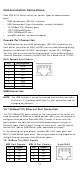
LED Color FAULT Re d P1 Am be r P2 Am be r M STR/ H EAD ( M/ H) Gr e e n CPLR/ TAI L Gr e e n St a t e D e scr ipt ion 1. The relay cont act has been t riggered 2. The ingress rat e lim it has On been exceeded and t he port has ent ered shut dow n m ode 3. I nvalid Ring port connect ion When t he syst em boot s up and runs correct ly or a userOff configured event is not t riggered. Pow er is being supplied t o pow er On input PWR. Pow er is not being supplied t o Off pow er input PWR.
LED Syst e m LED ( Ex ce pt PW R) Syst e m LED ( Ex ce pt PW R) Color Gr e e n + Am be r + Re d Gr e e n + Am be r + Re d St a t e D e scr ipt ion The sw it ch is being Blink ing discovered/ locat ed by t he locat or ( 2 t im e s/ se c) funct ion. Rot a t e On - > Off Se que nt ia lly The sw it ch is im port ing/ ex port ing a file via ABC- 02- USB or SD car d ( current ly disabled) .
Spe cifica t ions I nt e r fa ce RJ45 Port s Fiber Port s Console Port But t on LED I ndicat or s Alarm Cont act Digit al I nput 10/ 100/ 1000BaseT( X) 100/ 1000BaseSFP 1000/ 2500BaseSFP RS- 232 ( RJ45) Reset but t on STATE ( S) , FAULT ( F) , PWR1 ( P1) , PWR2 ( P2) , MSTR/ HEAD ( M/ H) , CPLR/ TAI L ( C/ T) , SYNC 1 nor m ally open elect rom agnet ic r elay out put w it h current carrying capacit y of 1 A @ 24 VDC 1 isolat ed digit al input : + 13 t o + 30V for st at e “ 1” - 30 t o + 3V for st at e “ 0”
I nst allat ion DI N- rail m ount ing, w all m ount ing ( w it h opt ional kit ) Envir on m e nt a l Lim it s Operat ing - 10 t o 60° C ( 14 t o 140° F) for st andard m odels Tem perat ure - 40 t o 75° C ( - 40 t o 167° F) for - T m odels St orage - 40 t o 85° C ( - 40 t o 185° F) Tem perat ure Am bient Relat ive 5 t o 95% ( non- condensing) Hum idit y Alt it ude Up t o 2000 m Not e: Please cont act Moxa if y ou r equire product s guarant eed t o funct ion pr operly at higher alt it ude.