EDS-4014 Series Quick Installation Guide Moxa EtherDevice™ Switch Version 1.0, March 2022 Technical Support Contact Information www.moxa.com/support 2022 Moxa Inc. All rights reserved.
Package Checklist The EDS-4014 Series industrial DIN-rail EtherDevice Switch (EDS) is shipped with the following items. If any of these items are missing or damaged, please contact your customer service representative for assistance.
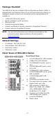
Bottom Panel View 1. 2. 3.
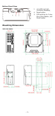
DIN-rail Mounting The DIN-rail mounting kit is fixed to the back panel of the EDS device when you take it out of the box. Mount the EDS device on corrosionfree mounting rails that meet the EN 60715 standard. Installation STEP 1—Insert the upper lip of the DIN rail into the DIN-rail mounting kit. STEP 2—Press the EDS device towards the DIN rail until it snaps into place. Removal STEP 1—Pull down the latch on the mounting kit with a screwdriver.
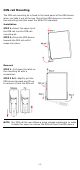
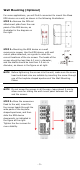
Wall Mounting (Optional) For some applications, you will find it convenient to mount the Moxa EDS device on a wall, as shown in the following illustrations: STEP 1—Remove the DIN rail attachment plate from the rear panel of the EDS device, as illustrated in the diagram on the right. STEP 2—Mounting the EDS device on a wall requires six screws. Use the EDS device, with wall mount plates attached, as a guide to mark the correct locations of the six screws. The heads of the screws should be less than 6.
Wiring Requirements ATTENTION Safety First! External metal parts are hot. Take the necessary precautions if you are required to handle the device. ATTENTION In order to ensure reliable operations, please make sure the operating temperature of the environment does not exceed the specifications. When mounting an EDS device with other operating units in a cabinet without forced ventilation, a minimum of 4 cm space on both the left and right of the switch is recommended.
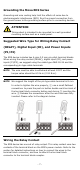
Grounding the Moxa EDS Series Grounding and wire routing help limit the effects of noise due to electromagnetic interference (EMI). Run the ground connection from the ground screw to the grounding surface prior to connecting devices. ATTENTION This product is intended to be mounted to a well-grounded mounting surface such as a metal panel. Suggested Wire Type for Wiring Relay Contact (RELAY), Digital Input (DI), and Power Inputs (P1/P2) The EDS device includes two 4-pins 3.5 mm pin-pitch terminal blocks.
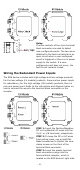
Relay: The two contacts of the 4-pin terminal block connector are used to detect user-configured events. The two wires attached to the fault contacts form an open circuit when a user-configured event is triggered or there is no power supply to the switch. If a userconfigured event does not occur, the fault circuit remains closed. Wiring the Redundant Power Inputs The EDS device includes both high-voltage and low-voltage products.
Wiring the Digital Inputs The EDS device has one set of digital input (DI). The DI consists of two contacts of the 4-pin terminal block connector on the EDS's right-side panel. Refer to the instructions and diagram below on how to connect the wires to the terminal block connector on the receptor. STEP 1: Insert the negative (ground)/positive DI wires into the ┴/I terminals, respectively.
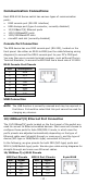
Communication Connections Each EDS-4014 Series switch has various types of communication ports: • • • • • • RJ45 console port (RS-232 interface) USB storage port (type A connector, currently disabled) 10/100BaseT(X) Ethernet ports 100/1000BaseSFP ports 1000/2500BaseSFP slots microSD card slot (currently disabled) Console Port Connection The EDS device has one RJ45 console port (RS-232), located on the front panel.
RJ45 (8-pin) to RJ45 (8-pin) Straight-through Cable Wiring RJ45 (8-pin) to RJ45 (8-pin) Cross-over Cable Wiring 100/1000BaseSFP and 1000/2500BaseSFP (mini-GBIC) Fiber Port The Gigabit Ethernet fiber ports on the switch are 100/1000BaseSFP and 1000/2500BaseSFP fiber ports, which must use 100M,1G, 2.5G mini-GBIC fiber transceivers to work properly. The concept behind the LC port and cable is quite straightforward.
ATTENTION This is a Class 1 Laser/LED product. To avoid causing serious damage to your eyes, do not stare directly into the Laser Beam. Reset Button There are two functions available on the Reset Button. One is to reset the Ethernet switch to factory default settings by pressing and holding the Reset button for 5 seconds. Use a pointed object, such as a straightened paper clip or toothpick, to depress the Reset button. This will cause the STATE LED to blink once a second.
DIP Switch Settings DIP 1 DIP 2 ON: Enables the default “Ring Coupling (backup)” port when DIP switch 4 Reserved is already enabled. for future OFF: Enables the use default Ring Coupling (primary) port when DIP switch 4 is already enabled. DIP 3 ON: Enables this EDS as the Ring Master. OFF: This EDS will not be the Ring Master. DIP 4 ON: Enables the default “Ring Coupling” port. OFF: This EDS will not be the Ring Coupler. DIP 5 ON: Activates DIP switch 2, 3, and 4 to configure Turbo Ring V2 settings.
LED Color FAULT Red P1 Amber P2 Amber MSTR/ HEAD (M/H) Green CPLR/ TAIL Green State Description 1. The relay contact has been triggered 2. The ingress rate limit has On been exceeded and the port has entered shut down mode 3. Invalid Ring port connection When the system boots up and runs correctly or a userOff configured event is not triggered. Power is being supplied to power On input PWR. Power is not being supplied to Off power input PWR. Power is being supplied to power On input PWR.
LED Color State System Green + LED Blinking Amber + (Except (2 times/sec) Red PWR) System Rotate Green + LED On -> Off Amber + (Except Sequentially Red PWR) Description The switch is being discovered/located by the locator function. The switch is importing/exporting a file via ABC-02-USB or SD card (currently disabled).
Specifications Interface RJ45 Ports Fiber Ports Console Port Button LED Indicators Alarm Contact Digital Input 10/100/1000BaseT(X) 100/1000BaseSFP 1000/2500BaseSFP RS-232 (RJ45) Reset button STATE (S), FAULT (F), PWR1 (P1), PWR2 (P2), MSTR/HEAD (M/H), CPLR/TAIL (C/T), SYNC 1 normally open electromagnetic relay output with current carrying capacity of 1 A @ 24 VDC 1 isolated digital input: +13 to +30V for state “1” -30 to +3V for state “0” Max.
Installation DIN-rail mounting, wall mounting (with optional kit) Environmental Limits Operating -10 to 60°C (14 to 140°F) for standard models Temperature -40 to 75°C (-40 to 167°F) for -T models Storage -40 to 85°C (-40 to 185°F) Temperature Ambient Relative 5 to 95% (non-condensing) Humidity Altitude Up to 2000 m Note: Please contact Moxa if you require products guaranteed to function properly at higher altitude.