Moxa EtherDevice™ Switch EDS-600 Series Hardware Installation Guide Second Edition, November 2010 2010 Moxa Inc. All rights reserved. Reproduction without permission is prohibited.
Package Checklist The Moxa EDS-600 series is shipped with the following items. If any of these items is missing or damaged, please contact your customer service representative for assistance.
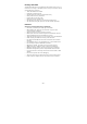
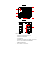
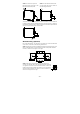
Panel Views of the EDS-608 Front Panel: 1. System Status LEDs 2. Fast Ethernet Interface Module port LEDs 3. Fast Ethernet Interface Module 4. Terminal block for 2 power inputs, 1 DI/DO, and 1 relay output 5. Grounding screw 6. DIP switches for Ring Master, Ring Coupler, and Turbo Ring 7. RS-232 Console port 8. Screw to attach Fast Ethernet Interface Module Rear Panel: 9. DIN-Rail Attachment Plate 10.
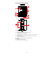
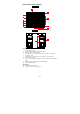
Panel Views of the EDS-611 Front Panel: 1. System Status LEDs 2. Fast Ethernet Interface Module port LEDs 3. Fast Ethernet Interface Module 4. Terminal block for 2 power inputs, 1 DI/DO, and 1 Relay output 5. Grounding screw 6. DIP switches for Ring Master, Ring Coupler, and Turbo Ring 7. RS-232 Console port 8. G1 to G3: 10/100/1000 BaseT(X) or 100/1000Base SFP slot combo ports 9. Screw to attach Fast Ethernet Interface Module 10. Gigabit Ethernet LEDs Rear Panel: 11. DIN-Rail Attachment Plate 12.
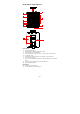
Panel Views of the EDS-616 Front Panel: 1. System Status LEDs 2. Fast Ethernet Interface Module port LEDs 3. Fast Ethernet Interface Module 4. Terminal block for 2 power inputs, 1 DI/DO, and 1 relay output 5. Grounding screw 6. DIP switches for Ring Master, Ring Coupler, and Turbo Ring 7. RS-232 Console port 8. Screw to attach Fast Ethernet Interface Module Rear Panel: 9. DIN-Rail Attachment Plate 10.
Panel Views of the EDS-619 Front Panel: 1. System Status LEDs 2. Fast Ethernet Interface Module port LEDs 3. Fast Ethernet Interface Module 4. Terminal block for 2 power inputs, 1 DI/DO, and 1 relay output 5. Grounding screw 6. DIP switches for Ring Master, Ring Coupler, and Turbo Ring 7. RS-232 Console port 8. G1 to G3: 10/100/1000 BaseT(X) or 100/1000Base SFP slot combo ports 9. Screw to attach Fast Ethernet Interface Module 10. Gigabit Ethernet LEDs Rear Panel: 11. DIN-Rail Attachment Plate 12.
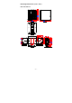
Mounting Dimensions (unit = mm) EDS-608/EDS-611 -7-
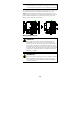
EDS-616/EDS-619 DIN-Rail Mounting The aluminum DIN-Rail attachment plate should already be fixed to the back panel of the EDS-600 when you take it out of the box. If you need to reattach the DIN-Rail attachment plate to the EDS-600, be sure the spring-loaded bracket is situated towards the bottom, as shown in the following figures. STEP 1: If the spring-loaded bracket is locked in place, push the recessed button to release it.
STEP 2—Insert the top of the DIN-Rail into the top slots on the DIN-Rail attachment plate. STEP 3—The DIN-Rail attachment unit will snap into place as shown in the following illustration. To remove the Moxa EDS-600 switch from the DIN-Rail, use a screwdriver to push down the spring-loaded bracket until it locks in place, as shown in the following diagram. Next, rotate the bottom of the switch upwards and then remove the switch from the DIN-Rail.
NOTE Before tightening the screws into the wall, make sure the screw head and shank size are suitable by inserting the screw through one of the keyhole-shaped apertures of the Wall Mounting Plates. Do not screw the screws in all the way—leave about 2 mm to allow room for sliding the wall mount panel between the wall and the screws.
ATTENTION Safety First! Be sure to disconnect the power cord before installing and/or wiring your Moxa EtherDevice Switch. Calculate the maximum possible current in each power wire and common wire. Observe all electrical codes dictating the maximum current allowable for each wire size. If the current goes above the maximum ratings, the wiring could overheat, causing serious damage to your equipment. Please read and follow these guidelines: • • • • Use separate paths to route wiring for power and devices.
ATTENTION This product is intended to be mounted to a well-grounded mounting surface such as a metal panel. Wiring the Relay Contact The EDS-600 has a set of relay outputs. The relay contact uses two of the terminal block’s contacts located on the EDS-600’s front panel. Refer to the next section for detailed instructions on how to connect the wires to the terminal block connector, and how to attach the terminal block connector to the terminal block receptor.
Wiring the Digital Inputs The EDS-600 has one set of digital inputs (DIs). Each DI consists of two contacts of the 5-pin terminal block connector on the EDS-600’s front panel, which are used for the one DC input. The top and front views of one of the terminal block connectors are shown here. STEP 1: Insert the negative (ground)/positive DI wires into the ┴/I1 terminals, respectively. • • • +13 to +30 V for state “1” -30 to +3 V for state “0” Max.
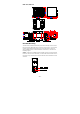
RJ45 (10-pin) to DB9 (F) Cable Wiring 10/100/1000BaseT(X) Ethernet Port Connection The 10/100/1000BaseT(X) ports located on switch’s front panel are used to connect to Ethernet-enabled devices. Most users will choose to configure these ports for Auto MDI/MDI-X mode, in which case the port’s pinouts are adjusted automatically depending on the type of Ethernet cable used (straight-through or cross-over), and the type of device (NIC-type or HUB/Switch-type) connected to the port.
RJ45 (8-pin) to RJ45 (8-pin) Straight-through Cable Wiring RJ45 (8-pin) to RJ45 (8-pin) Cross-over Cable Wiring 100BaseFX or 1000BaseSFP Fiber Port The Gigabit Ethernet ports on the EDS-600 series are SFP slots, which require 100BaseFX SFP or Gigabit mini-GBIC fiber transceivers to work properly. Moxa provides complete transceiver models for various distance requirements. The concept behind the LC port and cable is quite straightforward. Suppose you are connecting devices 1 and 2.
ATTENTION This is a Class 1 Laser/LED product. To avoid causing serious damage to your eyes, do not stare directly into the laser beam. Turbo Ring DIP Switch Settings EDS-600 series switches are managed redundant plug-and-play Ethernet switches. The proprietary Turbo Ring protocol was developed by Moxa to provide better network reliability and faster recovery time.
“Turbo Ring V2” DIP Switch Settings DIP 1 ON: Enables the default “Ring Coupling (backup)” port. DIP 2 ON: Enables this EDS as the Ring Master. OFF: Enables the OFF: This EDS will not be the default “Ring Ring Master. Coupling (primary)” port. DIP 3 ON: Enables the default “Ring Coupling” port. DIP 4 ON: Activates DIP switches 1, 2, 3 to configure “Turbo Ring V2” settings. OFF: Do not use OFF: DIP this EDS as a ring switches 1, 2, 3 coupler. will be disabled.
CPLR/ TAIL GREEN On Blinking Off G1/G2/G3 (EDS-611/ EDS-619 only) AMBER GREEN 10/100M AMBER Green On Blinking When the EDS-600 coupling function is enabled to form a back-up path or if it is set as the Tail of the Turbo Chain. When the Turbo Chain is down. To disable the EDS-600’s coupling function. 10/100 Mbps link is active. Data is being transmitted at 10/100 Mbps. Off 10/100 Mbps link is inactive. On Blinking 1000 Mbps link is active. Data is being transmitted at 1000 Mbps.
Digital Input Power Input Voltage Input Current (@24V) Two inputs with the same ground, but electrically isolated from the electronics • For state “1”: +13 to +30 V • For state “0”: -30 to +3 V • Max. input current: 8 mA 12/24/48 VDC, redundant inputs EDS-608: 0.16A EDS-611: 0.31A EDS-616: 0.25A EDS-619: 0.
Vibration WARRANTY IEC60068-2-6 5 years Technical Support Contact Information www.moxa.