
Installation guide

- 12 -
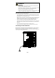
ATTENTION
This product is intended to be mounted to a well-grounded
mounting surface such as a metal panel.
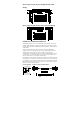
Wiring the Relay Contact
The EDS-600 has a set of relay outputs. The relay contact uses two of the
terminal block’s contacts located on the EDS-600’s front panel. Refer to
the next section for detailed instructions on how to connect the wires to
the terminal block connector, and how to attach the terminal block
connector to the terminal block receptor.
In this section, we illustrate the meaning of the two contacts used to
connect the relay contact.
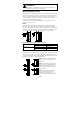
FAULT:
The relay contacts of the 6-pin terminal block connector are used to
detect user-configured events. The three wires attached to the fault
contacts form an open circuit when a user-configured event is triggered.
If a user-configured event does not occur, the fault circuit remains closed.
The relay output has current carrying capacity of 1 A @ 24 VDC.
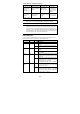
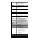
Relay Circuit Status when Power is On/Off
Power On COM & NC Open Circuit
COM & NO Short Circuit
Power Off COM & NC Short Circuit
COM & NO Open Circuit
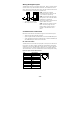
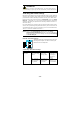
Wiring the Redundant Power Inputs
The EDS-600 has two sets of power inputs, power 1 and power 2, which
are located on the EDS-600’s front panel. Power 1 is the bottom two
contacts on the upper 6-contact terminal block and power 2 is the top two
contacts on the lower 5-contact terminal block.
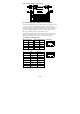
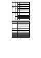
STEP 1: Insert the negative/positive
DC wires into the V-/V+ terminals,
respectively.
STEP 2: To keep the DC wires from
pulling loose, use a small flat-blade
screwdriver to tighten the wire-clamp
screws on the front of the terminal
block connector.
STEP 3: Insert the plastic terminal
block connector prongs into the
terminal block receptor, which is
located on the EDS-600’s front panel.