ED S- G4 0 0 8 Se rie s Quick I nst a lla t ion Guide M ox a Et he r D e vice ™ Sw it ch Ve r sion 1 .0 , M a r ch 2 0 2 2 Te chnica l Suppor t Con t a ct I nfor m a t ion w w w .m ox a . com / suppor t 2022 Moxa I nc. All right s reserv ed.
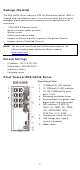
Pa ck a ge Che ck list The EDS- G4008 Series indust rial DI N- rail Et herDevice Sw it ch ( EDS) is shipped w it h t he follow ing it em s. I f any of t hese it em s are m issing or dam aged, please cont act y our cust om er service represent at ive for assist ance.
Bot t om Pa ne l Vie w 1. 2. 3.
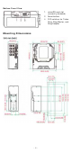
D I N - r a il M ount ing The DI N- rail m ount ing k it is fixed t o t he back panel of t he EDS device w hen you t ake it out of t he box. Mount t he EDS device on corrosionfree m ount ing rails t hat m eet t he EN 60715 st andard. I nst a lla t ion STEP 1 —I nsert t he upper lip of t he DI N rail int o t he DI N- rail m ount ing kit . STEP 2 —Press t he EDS device t ow ards t he DI N rail unt il it snaps int o place. Re m ova l STEP 1 —Pull dow n t he lat ch on t he m ount ing kit w it h a screw driver.
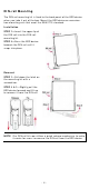
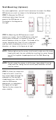
W a ll M ount ing ( Opt iona l) For som e applicat ions, y ou w ill find it convenient t o m ount t he Moxa EDS device on a w all, as show n in t he follow ing illust rat ions: STEP 1 —Rem ove t he DI N- rail at t achm ent plat e fr om t he rear panel of t he EDS device, as illust rat ed in t he diagram on t he right . STEP 2 —Mount ing t he EDS device on a w all requires six screw s.
W ir ing Re quir e m e nt s ATTEN TI ON Sa fe t y Fir st ! Ext ernal m et al part s are hot . Take t he necessar y precaut ions if you are required t o handle t he device. ATTEN TI ON I n order t o ensure reliable operat ions, please m ake sure t he operat ing t em perat ure of t he environm ent does not exceed t he specificat ions.
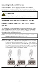
Gr oun ding t he M ox a ED S Se r ie s Grounding and w ire r out ing help lim it t he effect s of noise due t o elect rom agnet ic int erference ( EMI ) . Run t he ground connect ion from t he ground screw t o t he grounding surface prior t o connect ing devices. ATTEN TI ON This product is int ended t o be m ount ed t o a w ell- gr ounded m ount ing surface such as a m et al panel.
W ir ing t he Re la y Cont a ct The EDS device has one set of relay out put . This relay cont act uses t w o cont act s of t he t erm inal block on t he EDS’s pow er m odule. Refer t o t he sect ion for det ailed inst ruct ions on how t o connect t he w ires t o t he t erm inal block connect or, and how t o at t ach t he t er m inal block connect or t o t he t erm inal block recept or. Re la y: The t w o cont act s of t he 4- pin t erm inal block connect or are used t o det ect user- configured event s.
STEP 1 : I nsert t he Posit ive/ Negat ive DC or Line/ Neut ral AC w ires int o t he V+ / V- or L/ N t erm inals, respect ively. STEP 2 : To keep t he DC or AC w ires from pulling loose, use a sm all flat blade screw driver t o t ight en t he w ireclam p screw s on t he front of t he t erm inal block connect or. STEP 3 : I nsert t he plast ic t erm inal block connect or prongs int o t he t erm inal block recept or, w hich is locat ed on t he EDS devices’ right side.
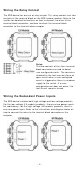
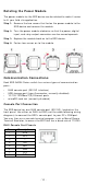
Rot a t ing t he Pow e r M odule The pow er m odule for t he EDS device can be rot at ed t o m ake it easier t o fit y our field sit e applicat ion. St e p 1 : Rem ove t he t w o screw s t hat fast en t he pow er m odule t o t he EDS device and rem ove t he m odule. St e p 2 : Turn t he pow er m odule clockw ise so t hat t he pow er, digit al input , and relay out put connect ors can be m oved upw ards. St e p 3 : Replace t he m odule back on t o t he EDS device.
USB Conn e ct ion N OTE The USB funct ion is current ly reserved and m ay be required in t he fut ure. I t should be not ed t hat t his port cannot be used for charging any devices. 1 0 0 0 Ba se T( X) Et h e r n et Por t Conn e ct ion 1000BaseT( X) dat a is t ransm it t ed on different ial TRD+ / - signal pair s over copper w ires.
Tur bo Ring D I P Sw it ch Se t t ings The default set t ing for each DI P Sw it ch is OFF. The follow ing t able explains t he effect of set t ing t he DI P Sw it ch t o t he ON posit ion. Rem ove t he rubber cover on t he bot t om panel of t he device t o expose t he DI P sw it ches. D I P Sw it ch Se t t ings DI P 1 DI P 2 ON : Enables t he default “ Ring Coupling ( backup) ” port w hen DI P sw it ch 4 Reserved is already enabled.
LED Color Re d FAULT Re d P1 Am be r P2 Am be r M STR/ H EAD ( M/ H) Gr e e n CPLR/ TAI L Gr e e n St a t e D e scr ipt ion The syst em has init ially failed t he boot - up process On • Syst em I nfo. Read Fail or EEPROM infor m at ion error 1. The relay cont act has been t riggered 2. The ingress rat e lim it has been exceeded and t he port On has ent ered shut dow n m ode 3.
LED Syst e m LED ( Ex ce pt PW R) Syst e m LED ( Ex ce pt PW R) Color St a t e D e scr ipt ion 1. The sw it ch is set as t he Tail of Tur bo Chain and t he Chain has gone dow n. Blink ing 2. The sw it ch is set as t he ( 4 t im e s/ se c) Turbo Chain’s Mem ber/ Head and t he corresponding Tail- end Chain port is dow n. When t he sw it ch disables t he Off coupling or t ail r ole of Turbo Chain.
Not e The EDS- G4008 Series support s m odular pow er supplies. The m odel nam es and pow er param et ers are det erm ined by t he inst alled pow er m odule. For exam ple: EDS- G4008- T + PWR- 100- LV = EDS- G4008- LV- T EDS- G4008- T + PWR- 105- HV- I = EDS- G4008- HVT Rat ed Volt age Operat ing Volt age Rat ed Current Pow er Consum pt ion I nrush Current I f y ou inst all a different pow er m odule, refer t o t he specificat ions of t he corresponding m odel.
EMS Shock Free Fall Vibrat ion Rail Traffic ( Wayside) Traffic Cont rol W arranty Warrant y EN 61000- 4- 2 ( ESD) Level 4 EN 61000- 4- 3 ( RS) Level 3 EN 61000- 4- 4 ( EFT) Level 4 EN 61000- 4- 5 ( Surge) Level 4 EN 61000- 4- 6 ( CS) Level 3 EN 61000- 4- 8 Level 4 I EC 60068- 2- 27 I EC 60068- 2- 32 I EC 60068- 2- 6 EN 50121- 4 NEMA TS2 5 years ATTEN TI ON This device com plies w it h Part 15 of t he FCC rules. Operat ion is subj ect t o t he follow ing condit ions: 1.