EDS-P510 Series User’s Manual Second Edition, June 2010 www.moxa.com/product © 2010 Moxa Inc. All rights reserved. Reproduction without permission is prohibited.
EDS-P510 Series User’s Manual The software described in this manual is furnished under a license agreement and may be used only in accordance with the terms of that agreement. Copyright Notice Copyright ©2010 Moxa Inc. All rights reserved. Reproduction without permission is prohibited. Trademarks The MOXA logo is a registered trademark of Moxa Inc. All other trademarks or registered marks in this manual belong to their respective manufacturers.
Table of Contents 1. Introduction...................................................................................................................................... 1-1 Overview ...........................................................................................................................................1-2 Package Checklist ...............................................................................................................................1-2 Features .............................
Configuring Line-Swap Fast Recovery .......................................................................................... 3-66 Using Set Device IP........................................................................................................................... 3-66 Configuring Set Device IP ........................................................................................................... 3-67 Using Diagnosis .............................................................................
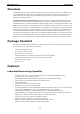
1 1. Introduction Welcome to the Moxa EDS-P510 Series of EtherDevice Switches, the PoE Gigabit Managed Redundant Ethernet Switches designed for connecting powered devices (PD) in industrial field applications.
EDS-P510 Series Introduction Overview As the world’s network and information technology becomes more mature, the trend is to use Ethernet as the major communications interface in many industrial communications and automation applications. In fact, a whole new industry has sprung up to provide Ethernet products that comply with the requirements of demanding industrial applications.
EDS-P510 Series Introduction Designed for Industrial Applications • Advanced PoE management function • Bandwidth management prevents unpredictable network status • Support ABC-01 (Automatic Backup Configurator) for system configuration backup • Long-haul transmission distance of 40 km or 80 km (with optional mini-GBIC) • Redundant, dual 46 to 50 VDC power inputs • IP30, rugged high-strength metal case • DIN-Rail or panel mounting ability • Bandwidth management to prevent unpredictable netwo
EDS-P510 Series • Introduction SFP-1G40BLC: WDM-type (BiDi) SFP module with 1 1000BaseSFP port with LC connector for 40 km transmission; TX 1550 nm, RX 1310 nm, 0 to 60°C operating temperature • SFP-1GSXLC-T: SFP module with 1 1000BaseSX port with LC conncector for 0.
2 2. Getting Started This chapter explains how to access the EDS-P510 for the first time. There are three ways to access the switch: serial console, Telnet console, and web browser. The serial console connection method, which requires using a short serial cable to connect the EDS-P510 to a PC’s COM port, can be used if you do not know the EDS-P510’s IP address. The Telnet console and web browser connection methods can be used to access the EDS-P510 over an Ethernet LAN, or over the Internet.
EDS-P510 Series Getting Started RS-232 Console Configuration (115200, None, 8, 1, VT100) Connection Caution! • • You cannot connect to the EDS-P510 simultaneously by serial console and Telnet. You can connect to the EDS-P510 simultaneously by web browser and serial console, or by web browser and Telnet. However, we strongly suggest that you do NOT use more than one connection method at the same time. Following this advice will allow you to maintain better control over the configuration of your EDS-P510.
EDS-P510 Series Getting Started 3. The Communication Parameter page of the Property window opens. Select the appropriate COM port for Console Connection, 115200 for Baud Rate, 8 for Data Bits, None for Parity, and 1 for Stop Bits. 4. Click the Terminal tab, and select VT100 for Terminal Type. Click OK to continue. 5. Type 1 to select ansi/VT100 terminal type, and then press Enter.
EDS-P510 Series Getting Started 6. The Console login screen will appear. Press Enter to open the Account pop-up selector and then select either admin or user. Use the keyboard’s down arrow to move the cursor to the Password field, enter the Console Password (this is the same as the Web Browser password; leave the Password field blank if a console password has not been set), and then press Enter. 7. The EDS-P510’s Main Menu will be displayed.
EDS-P510 Series Getting Started Configuration using a Telnet Console You may use Telnet to access the EDS-P510’s console utility over a network. To be able to access the EDS’s functions over the network (by Telnet or web browser) from a PC host that is connected to the same LAN as the EDS-P510, you need to make sure that the PC host and the EDS-P510 are on the same logical subnet. To do this, check your PC host’s IP address and subnet mask. By default, the EDS-P510’s IP address is 192.168.127.
EDS-P510 Series Getting Started 4. When the Main Menu of the EDS-P510’s console utility opens, click Terminal preferences… from the menu at the top of the window. 5. When the Terminal Preferences window opens, make sure that the VT100 Arrows option is selected. NOTE The Telnet Console looks and operates in precisely the same manner as the RS-232 Console.
EDS-P510 Series Getting Started 2. The web login page will open. Select the login account (Admin or User) and enter the Password (this is the same as the Console password), and then click Login to continue. Leave the Password field blank if a password has not been set. NOTE By default, the EDS-P510’s password is not set (i.e., is blank). 3. You may need to wait a few moments for the web page to be downloaded to your computer.
3 3. Featured Functions In this chapter, we explain how to access the EDS-P510’s configuration options, perform monitoring, and use administration functions. There are three ways to access these functions: RS-232 console, Telnet console, and web browser. The serial console connection method, which requires using a short serial cable to connect the EDS-P510 to a PC’s COM port, can be used if you do not know the EDS-P510’s IP address.
EDS-P510 Series Featured Functions Configuring Basic Settings The Basic Settings group includes the most commonly used settings required by administrators to maintain and control EDS-P510. System Identification The system identification items are displayed at the top of the web page, and will be included in alarm emails. Entering the system identification information makes it easier to identify the different switches connected to your network Switch Name Setting Description Factory Default Max.
EDS-P510 Series Featured Functions Password The EDS-P510 provides two levels of access privilege: admin privilege gives read/write access to all EDS-P510 configuration parameters, and user privilege provides read access only. You will be able to view the configuration, but will not be able to make modifications. ATTENTION The EDS-P510’s default Password is not set (i.e., is blank).
EDS-P510 Series Featured Functions Accessible IP Settings allows you to add or remove “Legal” remote host IP addresses to prevent unauthorized access. Access to the EDS-P510 is controlled by IP address. If a host’s IP address is in the accessible IP table, then the host will be allowed access to the EDS-P510. You can allow one of the following cases by setting this parameter: • Only one host with the specified IP address can access the EDS-P510 E.g., enter “192.168.1.1/255.255.255.
EDS-P510 Series Featured Functions Name Setting Description Factory Default Max. 63 Characters Specify an alias for each port, and assist the administrator in None remembering important information about the port. E.g., PLC 1 Speed Setting Description Factory Default Auto Allows the port to use the IEEE 802.3u protocol to negotiate Auto with connected devices. The port and connected devices will determine the best speed for that connection.
EDS-P510 Series Featured Functions See a brief explanation of each configuration item below. Auto IP Configuration Setting Description Factory Default Disable Set up the EDS-P510’s IP address manually. Disable By DHCP The EDS-P510’s IP address will be assigned automatically by the network’s DHCP server. By BOOTP The EDS-P510’s IP address will be assigned automatically by the network’s BOOTP server.
EDS-P510 Series Featured Functions Global Unicast Address Setting Description None Displays the IPv6 Global Unicast address. The network portion None Factory Default of the Global Unicast address can be configured by specifying the Global Unicast Prefix and using a EUI-64 interface ID in the low order 64 bits.
EDS-P510 Series Featured Functions Current Date Setting Description Factory Default User adjustable date. The date parameter allows configuration of the local date in None yyyy/mm/dd format. (yyyy/mm/dd) Daylight Saving Time Daylight saving time (also know as DST or summer time) involves advancing clocks (usually 1 hour) during the summer time to provide an extra hour of daylight in the afternoon. Start Date Setting Description Factory Default User adjustable date.
EDS-P510 Series Featured Functions IEEE 1588 PTP The following information is taken from the NIST website at http://ieee1588.nist.gov/intro.htm: Time measurement can be accomplished using the IEEE Standard for a Precision Clock Synchronization Protocol for Networked Measurement and Control Systems (IEEE 1588-2008) to synchronize real-time clocks incorporated within each component of the electrical power system for power automation applications.
EDS-P510 Series Featured Functions PTP Setting Operation IEEE 1588/PTP Setting Description Factory Default Operation Disable or enable IEEE 1588(PTP) operation Disable Configuration IEEE 1588/PTP Setting Description Factory Default Clock Mode Support software-based IEEE 1588(PTP) mode Disable Sync Interval Period for sending synchronization message (in seconds) Disable Sub-domain Name Support _DFLT(Default) domain only _DFLT Description Factory Default Status Setting Offset To Master
EDS-P510 Series Featured Functions Turbo Ring DIP Switch The Turbo Ring DIP Switch page allows users to disable the four DIP switches located on the EDS’s outer casing. When enabled, the DIP switches can be used to configure basic settings for either the “Turbo Ring” protocol or “Turbo Ring V2” protocol. A complete description of the settings is given below.
EDS-P510 Series NOTE Featured Functions The four DIP Switches are used to configure both the “Turbo Ring” and “Turbo Ring V2” protocols, depending on which protocol is active. To select which protocol the EDS will use, start the user interface software, and then use the left menu to navigate to the Communication Redundancy page. To use one of the Turbo Ring protocols for the EDS, select either “Turbo Ring” or “Turbo Ring V2” in the Redundancy Protocol drop-down box.
EDS-P510 Series Featured Functions System File Update—By Remote TFTP The EDS-P510 supports saving your configuration file to a remote TFTP server or local host to allow other EDS-P510 switches to use the same configuration at a later time, or saving the Log file for future reference. Loading pre-saved firmware or a configuration file from the TFTP server or local host is also supported for easy upgrading or configuration of the EDS-P510.
EDS-P510 Series NOTE Featured Functions Some operating systems will open the configuration file and log file directly in the web page. In such cases, right click Export to save as a file. Upgrade Firmware To import the firmware file of this EDS-P510, click Browse to select the firmware file already saved on your computer. The upgrade procedure will proceed automatically after clicking Import.
EDS-P510 Series Featured Functions The Factory Default function is included to give users a quick way of restoring EDS-P510’s configuration settings to their factory default values. This function is available in the Console utility (serial or Telnet), and Web Browser interface. NOTE After activating the Factory Default function, you will need to use the default network settings to re-establish a web-browser or Telnet connection with your EDS-P510.
EDS-P510 Series Featured Functions Configuring Port Trunking The Port Trunking Settings page is where ports are assigned to a trunk group. Step 1: Select the desired Trunk Group (Trk1, Trk2, Trk3). Step 2: Select the Trunk Type (Static or LACP). Step 3: Select the desired ports under Available Ports and click Up to add to the Trunk Group. Step 4: Select the desired ports under Member Ports and click Down to remove from the group.
EDS-P510 Series Featured Functions Trunk Table Setting Description Trunk group Displays the trunk type and trunk group. Member port Displays the member ports that belong to the trunk group. Status Success means port trunking is working properly. Fail means port trunking is not working properly. Standby means port trunking is working as a standby port. When there are more than eight ports trunked as a trunking group, the 9th port will be the standby port.
EDS-P510 Series Featured Functions These parameters are configured on the SNMP page. A more detailed explanation of each parameter is given below the figure. SNMP Versions Setting Description Factory Default V1, V2c, V3, or V1, V2c, Specifies the SNMP protocol version used to manage the or V3 only V1, V2c switch. V1, V2c Read Community Setting Description Max. 30 characters Specifies the community string to authenticate the SNMP agent Public Factory Default for read-only access.
EDS-P510 Series Featured Functions User Auth. Type (for SNMP V1, V2c, V3 and V3 only) Setting Description Factory Default No-Auth Allows the admin account and user account to access objects No MD5-Auth Authentication will be based on the HMAC-MD5 algorithms. without authentication. No 8-character passwords are the minimum requirement for authentication. SHA-Auth Authentication will be based on the HMAC-SHA algorithms. No 8-character passwords are the minimum requirement for authentication.
EDS-P510 Series Featured Functions 2nd Trap Server IP/Name Setting Description IP or name Specifies the IP address or name of the secondary trap server None Factory Default used by your network. 2nd Trap Community Setting Description Factory Default Max. 30 characters Specifies the community string to use for authentication.
EDS-P510 Series Featured Functions Port Setting Enable Setting Description Factory Default Checked Allows data and power transmission through the port Enable Unchecked Immediately shuts off port access Enable Setting Description Factory Default Auto The amount of power assigned is determined according to the Auto Power Limit class that is read from the powered device. Manual The user can set the power limit value that indicates the Auto maximum amount of power available to the port.
EDS-P510 Series Featured Functions Enable Setting Description Factory Default Checked Enables the port for a defined time period Disable Unchecked Disables the port for a defined time period Weekly Timetabling Day Setting Description Factory Default Checked Enables the port for a defined number of days Disable Unchecked Disables the port for a defined number of days Start/End Time Setting Description Factory Default Time for working period Allows users to enter the start and end time fo
EDS-P510 Series Featured Functions Email Warning Event Types can be divided into two basic groups: Power-Fail and PD-Failure. Port Events Warming e-mail is sent when... Power-Fail When actual PD power consumption exceeds related PD power limit setting. PD-Failure When the switch cannot receive a PD response after the defined period. PoE Relay Warning Events Settings Relay Warning Event Types can be divided into two basic groups: Power-Fail and PD-Failure. Port Events Warming e-mail is sent when..
EDS-P510 Series NOTE Featured Functions Turbo Ring V2 Turbo Ring Turbo Chain STP RSTP Topology Ring Ring Chain Ring, Mesh Ring, Mesh Recovery Time < 20 ms < 300 ms < 20 ms Up to 30 sec. Up to 5 sec Most of Moxa’s managed switches now support three proprietary Turbo Ring protocols: 1. “Turbo Ring” refers to the original version of Moxa’s proprietary redundant ring protocol, which has a recovery time of under 300 ms. 2.
EDS-P510 Series Featured Functions EtherDevice Switch Initial setup of a “Turbo Ring” or “Turbo Ring V2” ring PWR1 7 G3 PWR2 FAULT Turbo 6 Ring G2 MASTER COUPLER 5 G1 10/100/1000 G3 4 G2 G3 G1 10/100 3 7 6 G2 5 2 4 3 PoE 2 G1 1 1 PWR1 7 G3 PWR2 FAULT Turbo 6 Ring G2 MASTER COUPLER 5 G1 EtherDevice Switch EtherDevice Switch EDS-P510 PWR1 G3 7 PWR2 FAULT Turbo 6 Ring G2 MASTER COUPLER 5 G1 10/100/1000 10/100/1000 G3 1. Select any two ports as redundant ports.
EDS-P510 Series Featured Functions Determining the Redundant Path of a “Turbo Ring V2” Ring EtherDevice Switch Master PWR1 7 G3 PWR2 FAULT Turbo 6 Ring G2 MASTER COUPLER 5 G1 10/100/1000 G3 4 G2 G3 G1 10/100 3 7 6 G2 5 2 4 3 PoE 2 G1 1 1 EDS-P510 For a “Turbo Ring V2” ring, the backup segment is the Turbo 6 Ring G2 MASTER COUPLER 5 PWR1 EtherDevice Switch PWR2 FAULT G1 EtherDevice Switch segment connected to the 2nd redundant port on the master.
EDS-P510 Series Featured Functions The coupler switch (i.e., Switch A) will monitor switch B through the coupling control port to determine whether or not the coupling port’s backup path should be recovered.
EDS-P510 Series Featured Functions Dual-Ring for a “Turbo Ring V2” Ring PWR1 7 G3 PWR2 FAULT Turbo 6 Ring G2 MASTER COUPLER 5 G1 PWR1 7 G3 PWR2 FAULT Turbo 6 Ring G2 MASTER COUPLER 5 G1 10/100/1000 10/100/1000 G3 4 G3 G2 G3 EtherDevice Switch EtherDevice Switch Master 4 G2 G1 G3 G1 10/100 3 10/100 7 3 7 6 G2 6 5 2 G2 4 5 2 3 4 PoE 3 2 G1 1 PoE 2 1 G1 1 1 EDS-P510 EtherDevice Switch EDS-P510 PWR1 G3 7 PWR2 FAULT Turbo 6 Ring G2 MASTER C
EDS-P510 Series Featured Functions Configuring “Turbo Ring” Explanation of “Current Status” Items Now Active Shows which communication protocol is in use: Turbo Ring, Turbo Ring V2, RSTP, or none. Master/Slave Indicates whether or not this EDS is the Master of the Turbo Ring. (This field appears only when selected to operate in Turbo Ring or Turbo Ring V2 mode.) NOTE The user does not need to set the master to use Turbo Ring.
EDS-P510 Series Featured Functions Redundant Ports Setting Description Factory Default 1st Port Select any port of the EDS to be one of the redundant ports. port G2 2nd Port Select any port of the EDS to be one of the redundant ports.
EDS-P510 Series Featured Functions Ring 1/2—1st Ring Port Status Ring 1/2—2nd Ring Port Status The “Ports Status” indicators show Forwarding for normal transmission, Blocking if this port is connected to a backup path and the path is blocked, and Link down if there is no connection. Coupling—Mode Indicates either None, Dual Homing, or Ring Coupling. Coupling—Coupling Port status Indicates either Primary, or Backup.
EDS-P510 Series Featured Functions Coupling Mode Setting Description Factory Default Dual Homing Select this item to change to the Dual Homing configuration Primary Port: page port 1 Backup Port: port 2 Ring Coupling Select this item to change to the Ring Coupling (backup) (backup) configuration page Ring Coupling Select this item to change to the Ring Coupling (primary) (primary) configuration page port 1 port 1 Primary/Backup Port NOTE Setting Description Factory Default Primary Po
EDS-P510 Series Featured Functions 3. Connect the Head switch, Tail switch, and Member switches as shown in the diagram. The path connecting to the Head port is the main path, and the path connecting to the Tail port is the back up path of the Turbo Chain. Under normal conditions, packets are transmitted through the Head Port to the LAN Network. If any Turbo Chain path is disconnected, the Tail Port will be activated to continue packet transmission.
EDS-P510 Series Featured Functions The “Ports Status” indicators show Forwarding for normal transmission, Blocked if this port is connected to the Tail port as a backup path and the path is blocked, and Link down if there is no connection. Explanation of “Settings” Items Redundancy Protocol Setting Description Turbo Ring Select this item to change to the Turbo Ring configuration page. None Turbo Ring V2 Factory Default Select this item to change to the Turbo Ring V2 configuration page.
EDS-P510 Series NOTE Featured Functions The STP protocol is part of the IEEE Std 802.1D, 1998 Edition bridge specification. The following explanation uses bridge instead of switch. What is STP? STP (802.1D) is a bridge-based system that is used to implement parallel paths for network traffic. STP uses a loop-detection process to: • Locate and then disable less efficient paths (i.e., paths that have a lower bandwidth). • Enable one of the less efficient paths if the most efficient path fails.
EDS-P510 Series Featured Functions STP will determine which path between each bridged segment is most efficient, and then assigns a specific reference point on the network. When the most efficient path has been identified, the other paths are blocked. In the previous 3 figures, STP first determined that the path through Bridge C was the most efficient, and as a result, blocked the path through Bridge B. After the failure of Bridge C, STP re-evaluated the situation and opened the path through Bridge B.
EDS-P510 Series Featured Functions Bridge will flow through the Designated Bridge. The port on this bridge that connects to the segment is called the Designated Bridge Port. STP Configuration After all the bridges on the network agree on the identity of the Root Bridge, and all other relevant parameters have been established, each bridge is configured to forward traffic only between its Root Port and the Designated Bridge Ports for the respective network segments.
EDS-P510 Series • Featured Functions Since Bridge A is the Root Bridge, it is also the Designated Bridge for LAN segment 1. Port 1 on Bridge A is selected as the Designated Bridge Port for LAN Segment 1. • Ports 1 of Bridges B, C, X, and Y are all Root Ports sine they are nearest to the Root Bridge, and therefore have the most efficient path. • Bridges B and X offer the same Root Path Cost for LAN segment 2.
EDS-P510 Series Featured Functions Configuring STP/RSTP The following figures indicate which Spanning Tree Protocol parameters can be configured. A more detailed explanation of each parameter follows. At the top of this page, the user can check the “Current Status” of this function. For RSTP, you will see: Now Active: This will show which communication protocol is being used—Turbo Ring, RSTP, or neither. Root/Not Root This field will appear only when selected to operate in RSTP mode.
EDS-P510 Series Featured Functions Max. Age (sec.) Setting Description Factory Default Numerical value input If this device is not the root, and it has not received a hello 20 by user message from the root in an amount of time equal to “Max. Age,” then this device will reconfigure itself as a root. Once two or more devices on the network are recognized as a root, the devices will renegotiate to set up a new Spanning Tree topology.
EDS-P510 Series Featured Functions Step 2: Assign a value to “Forwarding Delay” and then calculate the right most part of Eq. 4 to get the upper limit for “Max. Age.” Step 3: Assign a value to “Forwarding Delay” that satisfies the conditions in Eq. 3 and Eq. 4. Using Traffic Prioritization EDS-P510’s traffic prioritization capability provides Quality of Service (QoS) to your network by making data delivery more reliable.
EDS-P510 Series Featured Functions 4 Controlled Load (streaming multimedia) 5 Video (interactive media); less than 100 milliseconds of latency and jitter 6 Voice (interactive voice); less than 10 milliseconds of latency and jitter 7 Network Control Reserved traffic Even though the IEEE 802.
EDS-P510 Series • Featured Functions Weight Fair: This method services all the traffic queues, giving priority to the higher priority queues. Under most circumstances, this method gives high priority precedence over low-priority, but in the event that high-priority traffic exceeds the link capacity, lower priority traffic is not blocked. • Strict: This method services high traffic queues first; low priority queues are delayed until no more high priority data needs to be sent.
EDS-P510 Series Featured Functions Inspect TOS Setting Description Factory Default Enable/Disable Select the option to enable EDS-P510 to inspect the Type of Enable Service (TOS) bits in IPV4 frame to determine the priority of each frame. Inspect COS Setting Description Factory Default Enable/Disable Select the option to enable EDS-P510 to inspect the 802.1p Enable COS tag in the MAC frame to determine the priority of each frame.
EDS-P510 Series Featured Functions TOS/DiffServ Mapping Setting Description Factory Default Low/Normal/ Set the mapping table of different TOS values to 4 different 1 to 16: Low Medium/High egress queues. 17 to 32: Normal 33 to 48: Medium 49 to 64: High Using Virtual LAN Setting up Virtual LANs (VLANs) on your EDS-P510 increases the efficiency of your network by dividing the LAN into logical segments, as opposed to physical segments. In general, VLANs are easier to manage.
EDS-P510 Series Featured Functions Benefits of VLANs The main benefit of VLANs is that they provide a network segmentation system that is far more flexible than traditional networks. Using VLANs also provides you with three other benefits: • VLANs ease the relocation of devices on networks: With traditional networks, network administrators spend most of their time dealing with moves and changes. If users move to a different subnetwork, the addresses of each host must be updated manually.
EDS-P510 Series Featured Functions Communication between VLANs If devices connected to a VLAN need to communicate to devices on a different VLAN, a router or Layer 3 switching device with connections to both VLANs needs to be installed. Communication between VLANs can only take place if they are all connected to a routing or Layer 3 switching device. VLANs: Tagged and Untagged Membership The EDS-P510 supports 802.
EDS-P510 Series Featured Functions In this application, • Port 1 connects a single untagged device and assigns it to VLAN 5; it should be configured as “Access Port” with PVID 5. • Port 2 connects a LAN with two untagged devices belonging to VLAN 2. One tagged device with VID 3 and one tagged device with VID 4. It should be configured as “Trunk Port” with PVID 2 for untagged device and Fixed VLAN (Tagged) with 3 and 4 for tagged device.
EDS-P510 Series Featured Functions VLAN Mode Setting Description Factory Default 802.1Q VLAN Set VLAN mode to 802.1Q VLAN 802.1Q VLAN Port-based VLAN Set VLAN mode to Port-based VLAN Management VLAN ID Setting Description Factory Default VLAN ID Set the management VLAN of this EDS-P510. 1 Setting Description Factory Default Access This port type is used to connect single devices without tags. Access Trunk Select “Trunk” port type to connect another 802.
EDS-P510 Series Featured Functions VLAN Mode Setting Description Factory Default 802.1Q VLAN Set VLAN mode to 802.1Q VLAN 802.1Q VLAN Port-based VLAN Set VLAN mode to Port-based VLAN Port Setting Description Factory Default Enable/Disable Set port to specific VLAN Group. Enable (all ports belong to VLAN1) VLAN Table In 802.
EDS-P510 Series Featured Functions Using Multicast Filtering Multicast filtering improves the performance of networks that carry multicast traffic. This section explains multicasts, multicast filtering, and how multicast filtering can be implemented on your EDS-P510. The Concept of Multicast Filtering What is an IP Multicast? A multicast is a packet sent by one host to multiple hosts. Only those hosts that belong to a specific multicast group will receive the multicast.
EDS-P510 Series Featured Functions Network without multicast filtering Group 1 Multicast Stream IGMP Group2 Group 2 Multicast Stream IGMP Group1 IGMP Group2 IGMP Group1 All hosts receive the multicast traffic, even if they don’t need it.
EDS-P510 Series NOTE Featured Functions The EDS-P510 is compatible with any device that conforms to the IGMP v2 device protocol. IGMP Multicast Filtering IGMP is used by IP-supporting network devices to register hosts with multicast groups. It can be used on all LANs and VLANs that contain a multicast capable IP router, and on other network devices that support multicast filtering. IGMP works as follows: 1.
EDS-P510 Series Featured Functions IGMP Snooping Settings IGMP Snooping Enable Setting Description Factory Default Enable/Disable Select the option to enable the IGMP Snooping function Disabled globally.
EDS-P510 Series Featured Functions Static Multicast Router Port Setting Description Factory Default Select/Deselect Select the option to select which ports will connect to the Disabled multicast routers. It’s active only when IGMP Snooping is enabled. NOTE At least one switch must be designated the Querier or enable IGMP snooping and GMRP when enabling Turbo Ring and IGMP snooping simultaneously. IGMP Table The EDS-P510 displays the current active IGMP groups that were detected.
EDS-P510 Series Featured Functions Configuring GMRP GMRP is a MAC-based multicast management protocol, whereas IGMP is IP-based. GMRP provides a mechanism that allows bridges and end stations to register or un-register Group membership information dynamically. GMRP enable Setting Description Enable/Disable Select the option to enable the GMRP function for the port listed Disable Factory Default in the Port column GMRP Table The EDS-P510 displays the current active GMRP groups that were detected.
EDS-P510 Series Featured Functions Traffic Rate Limiting Settings Ingress Setting Description Factory Default Ingress rate Select the ingress rate for all packets from the following N/A options: Not Limited, 128K, 256K, 512K, 1M, 2M, 4M, 8M Using Port Access Control The EDS-P510 provides two kinds of Port-Based Access Controls. One is Static Port Lock and the other is IEEE 802.1X. Static Port Lock The EDS-P510 can also be configured to protect static MAC addresses for a specific port.
EDS-P510 Series Featured Functions external RADIUS server as the authentication server, or implement the authentication server in the EDS-P510 by using a Local User Database as the authentication look-up table. When we use an external RADIUS server as the authentication server, the authenticator and the authentication server exchange EAP frames between each other. Authentication can be initiated either by the supplicant or the authenticator.
EDS-P510 Series Featured Functions Configuring Static Port Lock The EDS-P510 supports adding unicast groups manually if required. MAC Address and Port Setting Description Factory Default MAC Address Add the static unicast MAC address into the address table. None Port Fix the static address with a dedicated port. 1 Configuring IEEE 802.1X Database Option Setting Description Local Select this option when setting the Local User Database as the Local Factory Default (Max.
EDS-P510 Series Featured Functions Shared Key Setting Description Factory Default alphanumeric (Max. 40 A key to be shared between the external RADIUS server and characters) None the EDS-P510. Both ends must be configured to use the same key. Re-Auth Setting Description Factory Default Enable/Disable Select to require re-authentication of the client after a preset Disable time period of no activity has elapsed.
EDS-P510 Series Featured Functions Local User Database Setup When setting the Local User Database as the authentication database, set the database first. Local User Database Setup Setting Description Factory Default User Name User Name for Local User Database None Password for Local User Database None Description for Local User Database None (Max. 30 characters) Password (Max. 16 characters) Description (Max. 30 characters) NOTE The user name for the Local User Database is case-insensitive.
EDS-P510 Series Featured Functions Using Auto Warning Since industrial Ethernet devices are often located at the endpoints of a system, these devices will not always know what is happening elsewhere on the network. This means that an industrial Ethernet switch that connects to these devices must provide system maintainers with real-time alarm messages.
EDS-P510 Series DI1 (OnOff) Featured Functions Digital Input 1 is triggered by on to off transition DI1 (OffOn) Digital Input 1 is triggered by off to on transition DI2 (OnOff) Digital Input 2 is triggered by on to off transition DI2 (OffOn) Digital Input 2 is triggered by off to on transition Configuration Change Activated A configuration item has been changed. Authentication Failure An incorrect password is entered. Comm.
EDS-P510 Series Featured Functions Mail Server IP/Name Setting Description Factory Default IP address The IP Address of your email server. None Setting Description Factory Default Max.
EDS-P510 Series Featured Functions Event Setup Event Types can be divided into two basic groups: System Events and Port Events. System Events are related to the overall function of the switch, whereas Port Events are related to the activity of a specific port. The EDS-P510 supports two relay outputs. You can configure which relay output is related to which events. This helps administrators identify the importance of the different events.
EDS-P510 Series Featured Functions Warning List Use this table to see if any relay alarms have been issued. Using Line-Swap-Fast-Recovery The Line-Swap Fast Recovery function, which is enabled by default, allows the EDS-P510 to return to normal operation extremely quickly after devices are unplugged and then re-plugged into different ports.
EDS-P510 Series Featured Functions STEP 1 Set up those Ethernet-enabled devices connected to the EDS-P510 for which you would like IP addresses to be assigned automatically. The devices must be configured to obtain their IP address automatically. The devices’ configuration utility should include a setup page that allows you to choose an option similar to Obtain an IP address automatically. For example, Windows’ TCP/IP Properties window is shown at the right.
EDS-P510 Series Featured Functions DHCP Option 82 Option 82 is used by the relay agent to insert additional information into the client’s DHCP request. The Relay Agent Information option is inserted by the DHCP relay agent when forwarding client-originated DHCP packets to a DHCP server. Servers can recognize the Relay Agent Information option and use the information to implement IP addresses to Clients.
EDS-P510 Series Featured Functions 2nd Server Setting Description Factory Default IP address for the 2nd This assigns the IP address of the 2nd DHCP server that the None DHCP server switch tries to access. 3rd Server Setting Description Factory Default IP address for the 3rd This assigns the IP address of the 3rd DHCP server that the None DHCP server switch tries to access.
EDS-P510 Series Featured Functions Mirror Port The Mirror port function can be used to monitor data being transmitted through a specific port. This is done by setting up another port (the mirror port) to receive the same data being transmitted from, or both to and from, the port under observation. This allows the network administrator to “sniff” the observed port and thus keep tabs on network activity.
EDS-P510 Series Featured Functions PC keyboard, the actual ping command originates from the EDS-P510 itself. In this way, the user can essentially control the EDS-P510 and send ping commands out through its ports. To use the Ping function, type in the desired IP address, and then press Enter from the Console utility, or click Ping when using the Web Browser interface. LLDP Function Overview Defined by IEEE 802.
EDS-P510 Series Featured Functions LLDP Table Port Neighbor ID Neighbor Port Neighbor Port Description Neighbor System Port: The port number that connects to the neighbor device. Neighbor ID: A unique entity which identifies a neighbor device; this is typically the MAC address. Neighbor Port: The port number of the neighbor device. Neighbor Port Description: A textual description of the neighbor device’s interface. Neighbor System: Hostname of the neighbor device.
EDS-P510 Series Featured Functions bar is being viewed. That is, as time progresses, the height of the bar moves up or down so that the user can view the change in the rate of packet transmission. The blue colored bar shows Unicast packets, the red colored bar shows Multicast packets, and the orange colored bar shows Broadcast packets. The graph is updated every few seconds, allowing the user to analyze data transmission activity in real-time.
EDS-P510 Series Featured Functions Using Event Log Bootup NOTE This field shows how many times the EDS-P510 has been rebooted or cold started. Date The date is updated based on how the current date is set in the “Basic Setting” page. Time The time is updated based on how the current time is set in the “Basic Setting” page. System Startup Time The system startup time related to this event. Events Events that have occurred.
EDS-P510 Series Featured Functions Syslog Server 1 Setting Description Factory Default IP Address Enter the IP address of 1st Syslog Server used by your None Port Destination Enter the UDP port of 1st Syslog Server. 514 Setting Description Factory Default IP Address Enter the IP address of 2nd Syslog Server used by your None network. (1 to 65535) Syslog Server 2 network. Port Destination Enter the UDP port of 2nd Syslog Server.
EDS-P510 Series Featured Functions 2. Warning messages will pop out to warn the user that the security certificate was issued by a company they have not chosen to trust. 3. Select Yes to enter the EDS-P510’s web browser interface and access the web browser interface secured via HTTPS/SSL. NOTE Moxa provides a Root CA certificate .After installing this certificate into your PC or notebook, you can access the web browser interface directly and will not see any warning messages again.
4 4. EDS Configurator GUI EDS Configurator is a comprehensive Windows-based GUI that is used to configure and maintain multiple EDS-P510 switches.
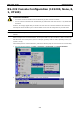
EDS-P510 Series EDS Configurator GUI Starting EDS Configurator To start EDS Configurator, locate and then run the executable file edscfgui.exe. NOTE You may download the EDS Configurator software from Moxa’s website at www.moxa.com. For example, if the file was placed on the Windows desktop, it should appear as follows. Simply double click on the icon to run the program. The Moxa EtherDevice Server Configurator window will open, as shown below.
EDS-P510 Series EDS Configurator GUI Once the search is complete, the Configurator window will display a list of all switches that were located. Search by IP address This utility is used to search for EDS-P510 switches one at a time. Note that the search is conducted by IP address, so you should be able to locate any EDS-P510 that is properly connected to your LAN, WAN, or even the Internet. Start by clicking the Specify by IP address icon the List Server menu.
EDS-P510 Series EDS Configurator GUI 3. Click the Upgrade Firmware toolbar icon , or select Upgrade under the Firmware menu. If the switch is Locked, you will be prompted to input the switch’s User Name and Password. 4. Use the Open window to navigate to the folder that contains the firmware upgrade file, and then click the correct “*.rom” file (eds.rom in the example shown below) to select the file. Click Open to activate the upgrade process.
EDS-P510 Series EDS Configurator GUI Export Configuration The Export Configuration utility is used to save the entire configuration of a particular EDS-P510 to a text file. Take the following steps to export a configuration: 1. Highlight the switch (from the Server list in the Configurator window’s left pane), and then click the Export or select Export Configuration from the Configuration menu.
EDS-P510 Series EDS Configurator GUI Import Configuration The Import Configuration function is used to import an entire configuration from a text file to the EDS-P510. This utility can be used to transfer the configuration from one EDS-P510 to another, by first using the Export Configuration function (described in the previous section) to save a switch configuration to a file, and then using the Import Configuration function. Perform the following steps to import a configuration: 1.
EDS-P510 Series EDS Configurator GUI Unlock Server The Unlock Server function is used to open a password protected switch so that the user can modify its configuration, import/export a configuration, etc. There are six possible responses under the Status column. The Status of an EDS-P510 indicates how the switch was located (by Moxa EtherDevice Switch Configurator), and what type of password protection it has.
A A. MIB Groups The EDS-P510 comes with built-in SNMP (Simple Network Management Protocol) agent software that supports cold/warm start trap, line up/down trap, and RFC 1213 MIB-II. The standard MIB groups that the EDS-P510 series support are: MIB II.1 – System Group sysORTable MIB II.2 – Interfaces Group ifTable MIB II.4 – IP Group ipAddrTable ipNetToMediaTable IpGroup IpBasicStatsGroup IpStatsGroup MIB II.5 – ICMP Group IcmpGroup IcmpInputStatus IcmpOutputStats MIB II.
EDS-P510 Series MIB Groups dot1dTpHCPortTable dot1dTpPortOverflowTable pBridgeMIB dot1dExtBase dot1dPriority dot1dGarp qBridgeMIB dot1qBase dot1qTp dot1qFdbTable dot1qTpPortTable dot1qTpGroupTable dot1qForwardUnregisteredTable dot1qStatic dot1qStaticUnicastTable dot1qStaticMulticastTable dot1qVlan dot1qVlanCurrentTable dot1qVlanStaticTable dot1qPortVlanTable The EDS-P510 also provides a private MIB file, located in the file “Moxa-EDSP510-MIB.my” on the EDS-P510 Series utility CD-ROM. Public Traps: 1.
B B.
EDS-P510 Series 0x0058 Modbus Information 1 word Power 1 0x0000:Off 0x0001:On 0x0059 1 word Power 2 0x0000:Off 0x0001:On 0x005A 1 word Fault LED Status 0x0000:No 0x0001:Yes 0x0080 1 word DI1 0x0000:Off 0x0001:On 0x0081 1 word DI2 0x0000:Off 0x0001:On 0x0082 1 word DO1 0x0000:Off 0x0001:On 0x0083 1 word DO2 0x0000:Off 0x0001:On Port Information 0x1000 to 0x1011 1 word Port 1 to 10 Status 0x0000:Link down 0x0001:Link up 0x0002:Disable 0xFFFF:No port 0x1100 to 0x1111 1 word Port 1 to
EDS-P510 Series 0x1400 to 0x1413(Port 1) Modbus Information 20 words Port 1 to 10 Description 0x1414 to 0x1427(Port 2) Port Description = "100TX,RJ45." Word 0 Hi byte = ‘1’ Word 0 Lo byte = ‘0’ Word 1 Hi byte = ‘0’ Word 1 Lo byte = ‘T’ … Word 4 Hi byte = ‘4’ Word 4 Lo byte = ‘5’ Word 5 Hi byte = ‘.
EDS-P510 Series 0x3300 Modbus Information 1 word TR Master/Slave 0x0000:Slave 0x0001:Master 0xFFFF:Turbo Ring Not Enable 0x3301 1 word TR 1st Port status 0x0000:Port Disabled 0x0001:Not Redundant 0x0002:Link Down 0x0003:Blocked 0x0004:Learning 0x0005:Forwarding 0x3302 1 word TR 2nd Port status 0x0000:Port Disabled 0x0001:Not Redundant 0x0002:Link Down 0x0003:Blocked 0x0004:Learning 0x0005:Forwarding 0x3303 1 word TR Coupling 0x0000:Off 0x0001:On 0xFFFF:Turbo Ring Not Enable 0x3304 1 word TR Co
EDS-P510 Series 0x3501 Modbus Information 1 word TR2 Coupling Port Primary status (Using in Dual Homing, Coupling Backup, Coupling Primary) 0x0000:Port Disabled 0x0001:Not Coupling Port 0x0002:Link Down 0x0003:Blocked 0x0004:Learning 0x0005:Forwarding 0xFFFF:Turbo Ring V2 Not Enable 0x3502 1 word TR2 Coupling Port Backup status (Only using in Dual Homing) 0x0000:Port Disabled 0x0001:Not Coupling Port 0x0002:Link Down 0x0003:Blocked 0x0004:Learning 0x0005:Forwarding 0xFFFF:Turbo Ring V2 Not Enable 0x36
EDS-P510 Series 0x3681 Modbus Information 1 word TR2 Ring 2 Master/Slave 0x0000:Slave 0x0001:Master 0xFFFF:Turbo Ring V2 Ring 2 Not Enable 0x3682 1 word TR2 Ring 2 1st Port status 0x0000:Port Disabled 0x0001:Not Redundant 0x0002:Link Down 0x0003:Blocked 0x0004:Learning 0x0005:Forwarding 0xFFFF:Turbo Ring V2 Ring 2 Not Enable 0x3683 1 word TR2 Ring 2 2nd Port status 0x0000:Port Disabled 0x0001:Not Redundant 0x0002:Link Down 0x0003:Blocked 0x0004:Learning 0x0005:Forwarding 0xFFFF:Turbo Ring V2 Ring 2