
User`s manual

EDS-P510 Series Featured Functions
3-26
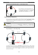
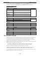
Determining the Redundant Path of a “Turbo Ring V2” Ring
Master
PWR1
PWR2
FAULT
7
6
5
4
3
2
1
G1
G2
G1
G3
G2
G3
EDS-P510
MASTER
G3
G2
G1
COUPLER
10/100/1000
7
6
5
4
3
2
1
10/100
EtherDevice Switch
Turbo
Ring
PoE
PWR1
PWR2
FAULT
7
6
5
4
3
2
1
G1
G2
G1
G3
G2
G3
EDS-P510
MASTER
G3
G2
G1
COUPLER
10/100/1000
7
6
5
4
3
2
1
10/100
EtherDevice Switch
Turbo
Ring
PoE
PWR1
PWR2
FAULT
7
6
5
4
3
2
1
G1
G2
G1
G3
G2
G3
EDS-P510
MASTER
G3
G2
G1
COUPLER
10/100/1000
7
6
5
4
3
2
1
10/100
EtherDevice Switch
Turbo
Ring
PoE
PWR1
PWR2
FAULT
7
6
5
4
3
2
1
G1
G2
G1
G3
G2
G3
EDS-P510
MASTER
G3
G2
G1
COUPLER
10/100/1000
7
6
5
4
3
2
1
10/100
EtherDevice Switch
Turbo
Ring
PoE
For a “Turbo Ring V2” ring, the backup segment is the
segment connected to the 2nd redundant port on the master.
See Configuring “Turbo Ring V2” in the Configuring
“Turbo Ring” and “Turbo Ring V2” section below.
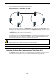
Ring Coupling Configuration
For some systems, it may not be convenient to connect all devices in the system to create one BIG redundant
ring, since some devices could be located in a remote area. For these systems, “Ring Coupling” can be used
to separate the devices into different smaller redundant rings, but in such a way that they can still
communicate with each other.
ATTENTION
In a VLAN environment, the user must set “Redundant Port” “Coupling Port” and “Coupling Control
Port” to join all VLANs, since these ports act as the “backbone” to transmit all packets of different VLANs to
different EDS units.
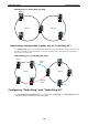
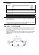
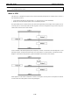
Ring Coupling for a “Turbo Ring” Ring
Switch A: "Coupler"
Switch B
Switch C
Switch D
Main Path
Coupling Port
Backup Path
Coupling
Control Port
PWR1
PWR2
FAULT
7
6
5
4
3
2
1
G1
G2
G1
G3
G2
G3
EDS-P510
MASTER
G3
G2
G1
COUPLER
10/100/1000
7
6
5
4
3
2
1
10/100
EtherDevice Switch
Turbo
Ring
PoE
PWR1
PWR2
FAULT
7
6
5
4
3
2
1
G1
G2
G1
G3
G2
G3
EDS-P510
MASTER
G3
G2
G1
COUPLER
10/100/1000
7
6
5
4
3
2
1
10/100
EtherDevice Switch
Turbo
Ring
PoE
PWR1
PWR2
FAULT
7
6
5
4
3
2
1
G1
G2
G1
G3
G2
G3
EDS-P510
MASTER
G3
G2
G1
COUPLER
10/100/1000
7
6
5
4
3
2
1
10/100
EtherDevice Switch
Turbo
Ring
PoE
PWR1
PWR2
FAULT
7
6
5
4
3
2
1
G1
G2
G1
G3
G2
G3
EDS-P510
MASTER
G3
G2
G1
COUPLER
10/100/1000
7
6
5
4
3
2
1
10/100
EtherDevice Switch
Turbo
Ring
PoE
PWR1
PWR2
FAULT
7
6
5
4
3
2
1
G1
G2
G1
G3
G2
G3
EDS-P510
MASTER
G3
G2
G1
COUPLER
10/100/1000
7
6
5
4
3
2
1
10/100
EtherDevice Switch
Turbo
Ring
PoE
PWR1
PWR2
FAULT
7
6
5
4
3
2
1
G1
G2
G1
G3
G2
G3
EDS-P510
MASTER
G3
G2
G1
COUPLER
10/100/1000
7
6
5
4
3
2
1
10/100
EtherDevice Switch
Turbo
Rin g
PoE
To configure the Ring Coupling function for a “Turbo Ring” ring, select two EDS units (e.g., Switch A and B in
the above figure) in the ring, and another two EDS units in the adjacent ring (e.g., Switch C and D). Decide
which two ports in each switch are appropriate to be used as coupling ports, and then link them together. Next,
assign one switch (e.g., Switch A) to be the “coupler” and connect the coupler’s coupling control port with
Switch B (for this example).