
User`s manual

EDS-P510 Series Featured Functions
3-32
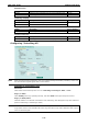
Coupling Mode
Setting Description Factory Default
Dual Homing Select this item to change to the Dual Homing configuration
page
Primary Port:
port 1
Backup Port:
port 2
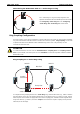
Ring Coupling
(backup)
Select this item to change to the Ring Coupling (backup)
configuration page
port 1
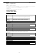
Ring Coupling
(primary)
Select this item to change to the Ring Coupling (primary)
configuration page
port 1
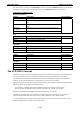
Primary/Backup Port
Setting Description Factory Default
Primary Port Select any port of the EDS to be the primary port. port 1
Backup Port Select any port of the EDS to be the backup port. port 2
NOTE The Turbo Ring DIP Switches located on the EDS-P510’s outer casing can be used to configure the EDS’s
Turbo Ring protocols. (For details on how to do this, refer to “Configuring Basic Settings—Turbo Ring DIP
Switch” section in this manual.)
If you use the web interface, console interface, or Telnet interface to enable the Turbo Ring DIP Switches, and
then set DIP Switch 4 on the switch’s outer casing to the “ON” position, you will not be able to use the web
interface, console interface, or Telnet interface to change the status of the DIP Switch. In this case, the
Communication Redundancy settings will be “grayed out” in the web browser.
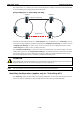
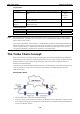
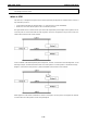
The Turbo Chain Concept
Moxa’s Turbo Chain is an advanced software-technology that gives network administrators the flexibility of
constructing any type of redundant network topology. When using the “chain” concept, you first connect the
Ethernet switches in a chain and then simply link the two ends of the chain to an Ethernet network, as
illustrated in the following figure.
Turbo Chain can be used on industrial networks that have a complex topology. If the industrial network uses a
multi-ring architecture, Turbo Chain can be used to create flexible and scalable topologies with a fast
media-recovery time.
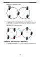
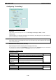
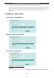
Setup Turbo Chain
1. Select the Head switch, Tail switch, and Member switches.
2. Configure one port as the Head port and one port as the Member port in the Head switch, configure one port
as the Tail port and one port as the Member port in the Tail switch, and configure two ports as Member ports
in each of the Member switches.