EM-1240 Hardware User’s Manual Fourth Edition, September 2008 www.moxa.com/product © 2008 Moxa Inc., All rights reserved. Reproduction without permission is prohibited.
EM-1240 Hardware User’s Manual The software described in this manual is furnished under a license agreement and may be used only in accordance with the terms of that agreement. Copyright Notice Copyright © 2008 Moxa Inc. All rights reserved. Reproduction without permission is prohibited. Trademarks MOXA is a registered trademark of Moxa Inc. All other trademarks or registered marks in this manual belong to their respective manufacturers.
Table of Contents Chapter 1 Introduction ..................................................................................................1-1 Overview.................................................................................................................................. 1-2 Package Checklist .................................................................................................................... 1-2 Product Features .....................................................................
1 Chapter 1 Introduction Thank you for purchasing the Moxa EM-1240 Embedded Module. The product’s features include 4 software-selectable RS-232/422/485 serial ports, two 10/100 Mbps Ethernet ports, and SD signals for external SD socket connection based on the Moxa ARM9 32-bit 192 MHz communication processor. These features make the EM-1240 ideal for the core module of an industrial embedded system design.
EM-1240 Hardware User’s Manual Introduction Overview The EM-1240 Embedded Module is designed for system integration and software development in industrial data applications. The module features 4 software-selectable RS-232/422/485 serial ports, two 10/100 Mbps Ethernet ports, and an SD function based on the Moxa ART ARM9 32-bit 192 MHz communication processor. In addition, you may order the EM-1240 Development Kit.
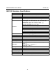
EM-1240 Hardware User’s Manual Introduction EM-1240 Hardware Specifications Model CPU RAM Flash EM-1240 Embedded Module Moxa ART ARM9 32-bit 192 MHz processor 16 MB 8 MB LAN Auto-sensing 10/100 Mbps × 2 Built-in 1.
EM-1240 Hardware User’s Manual Introduction EM-1240 Hardware Block Diagram Ethernet Power Circuit RTC LAN 1 LAN 2 PHY PHY MAC MAC 16 MB SDRAM 8 MB Flash MOXA ART CPU 32-bit ARM9 192 MHz Watchdog SD/GPIO Function UART UART UART UART UART Serial Port 1 Serial Port 2 Serial Console Port 4 Port Serial Port 3 RS-232 RS-232/422/485 Appearance EM-1240 Development Kit: EM-1240 Embedded Module + EM-1240-DK, carrier board of EM-1240 Development Kit 1-4
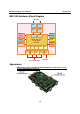
EM-1240 Hardware User’s Manual Introduction EM-1240 Embedded Module Top View Bottom View EM-1240 Development Kit 1-5
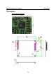
EM-1240 Hardware User’s Manual Introduction Dimensions EM-1240 Embedded Module 1-6
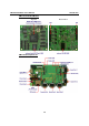
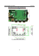
EM-1240 Hardware User’s Manual Introduction EM-1240-DK, Carrier board of EM-1240 Development Kit 1-7
2 Chapter 2 EM-1240 Functionality In this chapter, we explain the basic features of the EM-1240 Embedded Module.
EM-1240 Hardware User’s Manual EM-1240 Functionality EM-1240 Embedded Module Functions The EM-1240 Embedded Module is designed to be integrated directly into the user’s system and application. The module has four software-selectable RS-232/422/485 serial ports, dual 10/100 Mbps LAN ports, 1 RS-232 console port, and GPIO/SD signals. In addition, the EM-1240 uses the Moxa ART ARM9 32-bit 192 MHz communication processor, which ensures excellent performance for data transmission.
EM-1240 Hardware User’s Manual EM-1240 Functionality Pin Assignments There are two 56-pin pin headers on the EM-1240 embedded module. To use the EM-1240 Embedded Module to develop your own independent system, refer to the following tables for the pin assignments of jumpers JP3 and JP4.
EM-1240 Hardware User’s Manual Signals Eth0_TxD_outEth0_TxD_out+ Eth0_LED_100M Eth1_RxDjnEth1_RxDjn+ Eth1_LED_100M GPIO0 (I/O) GPIO2 (I/O) GPIO4 (I/O) GPIO6 (I/O) GPIO8 (I/O) Buzzer (Beeper) LED_Ready (SW_RDY) BLCM_DO (I/O) BLCM_D2 (I/O) BLCM_D4 (I/O) BLCM_D6 (I/O) D/I (LCM) (O) E (LCM) (O) CL (LCM) (O) CS1 (LCM) (O) GND KEY_OUT0 (KEYPAD) KEY_OUT2 (KEYPAD) KEY_OUT4 (KEYPAD) KEY_I N0 (KEYPAD) KEY_I N2 (KEYPAD) GND EM-1240 Functionality JP3 Pin No.
EM-1240 Hardware User’s Manual Signals GND VCC (5V) VCC (5V) GND GND RS-232: RxD0 RS-422: TXD0+ RS-485: X RS-232: RTS0 RS-422: X RS-485: X RS-232: DTR0 RS-422: RXD0RS-485: Data0RS-232: RxD1 RS-422: TXD1+ RS-485: X RS-232: CTS1 RS-422: X RS-485: X RS-232: DSR1 RS-422: X RS-485: X RS-232: DCD1 RS-422: TXD1RS-485: X RS-232: RxD2 RS-422: TXD2+ RS-485: X RS-232: DCD2 RS-422: TXD2RS-485: X RS-232: DTR2 RS-422: RXD2RS-485: Data2RS-232: RxD3 RS-422: TXD3+ RS-485: X RS-232: DCD3 RS-422: TXD3RS-485: X RS-232: DSR3 R
EM-1240 Hardware User’s Manual DTR_Console (RS-232) GND Serial LED_Tx0 Serial LED_Tx1 Serial LED_Tx2 Serial LED_Tx3 GND EM-1240 Functionality 43 45 47 49 51 53 55 44 46 48 50 52 54 56 DCD_Console (RS-232) GND Serial LED_Rx0 Serial LED_Rx1 Serial LED_Rx2 Serial LED_Rx3 GND Definition of SD Signals The following table gives the definition of the SD signals. Note that the signal pins from the JP3 pin header share the same pin as the GPIO.
3 Chapter 3 EM-1240-DK Functionality This chapter includes information about the EM-1240-DK (carrier board of the EM-1240 Development Kit).
EM-1240 Hardware User’s Manual EM-1240-DK Functionality EM-1240-DK Function The EM-1240 Development Kit is a well-designed PCB board with complete layout. The kit helps users evaluate, develop, and integrate the EM-1240 Embedded Module into their systems and applications. Simply combine the EM-1240 Embedded Module with the Development Kit to start porting the relevant software, and create a solution for the applications you wish to implement.
EM-1240 Hardware User’s Manual EM-1240-DK Functionality Wiring Requirements This section describes how to connect the EM-1240 Development Kit to serial devices. You should heed the following common safety precautions before proceeding with the installation of any electronic device: y Use separate paths to route wiring for power and devices. If power wiring and device wiring paths must cross, make sure the wires are perpendicular at the intersection point.
EM-1240 Hardware User’s Manual EM-1240-DK Functionality ATTENTION This product should be mounted to a well-grounded mounting surface such as a metal panel. SG V- SG: The Shielded Ground (sometimes called Protected Ground) contact is the left most contact of the 3-pin power terminal block connector when viewed from the angle shown here. Connect the SG wire to an appropriate grounded metal surface.
EM-1240 Hardware User’s Manual EM-1240-DK Functionality Console Ports and Pin Assignments The serial console port on the EM-1240-DK is an RS-232 port with full modem signal. It is designed for serial console terminals, which can be used for local configuration. PPP is also supported to make it easy to set up a modem connection for long distance data transmission. You may use the Pin header of the serial console port to extend the serial port to other devices.
EM-1240 Hardware User’s Manual EM-1240-DK Functionality GPIO The EM-1240 Development Kit has 10 GPIOs. You may configure digital input channels and digital output channels by software. Note that the GPIO function will not work if you enable the SD signals function. Use the GPIO pin header for connecting with devices. See the following figure for GPIO pinouts.