IA260 Hardware User’s Manual Third Edition, April 2009 www.moxa.com/product © 2009 Moxa Inc. All rights reserved. Reproduction without permission is prohibited.
IA260 Hardware User’s Manual Any software described in this manual is furnished under a license agreement and may be used only in accordance with the terms of that agreement. Copyright Notice Copyright © 2009 Moxa Inc. All rights reserved. Reproduction without permission is prohibited. Trademarks MOXA is a registered trademark of Moxa Inc. All other trademarks or registered marks in this manual belong to their respective manufacturers.
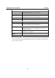
Table of Contents Chapter 1 Introduction ..................................................................................................1-1 Overview.................................................................................................................................. 1-2 Model Descriptions and Package Checklist............................................................................. 1-2 Product Features ......................................................................................
1 Chapter 1 Introduction Thank you for purchasing the Moxa IA260 RISC-based industrial ready-to-run embedded computer. This computer features 4 RS-232/422/485 serial ports, dual 10/100 Mbps Ethernet ports, 8 digital input and 8 digital output channels, a VGA output, a CompactFlash socket for adding additional storage space, and USB ports for a keyboard/mouse connection or for adding additional storage space.
IA260 Hardware User’s Manual Overview Overview The IA260 embedded computers feature 4 RS-232/422/485 serial ports, dual Ethernet ports, 8 digital input channels, 8 digital output channels, VGA output, 2 USB hosts and a CompactFlash socket in a compact, industrial-strength aluminum rugged casing. The DIN-Rail vertical form factor makes the IA260 a cost effective solution for installation in small cabinets.
IA260 Hardware User’s Manual Overview Both models are shipped with the following items: y 1 IA260 Embedded Computer y Wall-Mounting Kit y DIN-Rail Mounting Kit (attach to the product’s casing) y Quick Installation Guide y Document & Software CD y Ethernet Cable: RJ45 to RJ45 cross-over cable, 100 cm y CBL-4PINDB9F-100: 4-pin header to DB9 female console port cable, 100 cm y Universal Power Adaptor (includes terminal block to power jack converter) y Product Warranty Statement NOTE: Notify
IA260 Hardware User’s Manual Console/Debugging Port Overview RS-232 (TxD, RxD, GND), 4-pin header output (115200, n, 8, 1) Serial Communication Parameters 5, 6, 7, 8 Data Bits 1, 1.5, 2 Stop Bits None, Even, Odd, Space, Mark Parity RTS/CTS, XON/XOFF, ADDC™ (automatic data direction control) Flow Control for RS-485 50 bps to 921.
IA260 Hardware User’s Manual Environmental Limits Operating Temperature Operating Humidity Storage Temperature Anti-Vibration Anti-Shock Power Requirements Input Voltage Power Consumption Regulatory Approvals EMC Safety Automatic Reboot Trigger Warranty Overview Standard Models: -10 to 60°C (14 to 140°F) Wide Temp. Models: -40 to 75°C (-40 to 167°F) 5 to 95% RH Standard Models: -20 to 80°C (-4 to 176°F) Wide Temp.
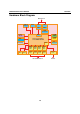
IA260 Hardware User’s Manual Overview Hardware Block Diagram Ethernet x 2 USB 2.
2 Chapter 2 Hardware Introduction The IA260 embedded computers are compact and rugged, making them suitable for industrial applications. The LED indicators allow users to monitor performance and identify trouble spots quickly, and the multiple ports can be used to connect a variety of devices. The IA260 comes with a reliable and stable hardware platform that lets you devote the bulk of your time to application development.
IA260 Hardware User’s Manual Hardware Introduction Appearance Top View Power Input (12 to 48 VDC) DO x 8 DI x 8 Reset Front View LED Indicators Power, Ready, Storage 4R LED Indicators T LED Indicators Serial, Tx/Rx Serial, Tx/Rx 10/100 Mbps Ethernet x 2 RS-232/422/485 Serial Port x 4 CompactFlash Socket VGA Output USB 2.
IA260 Hardware User’s Manual Hardware Introduction Rear View DIN-rail Kit Dimensions DC 12-48V GND DI7 DI6 DI5 DI4 DI3 DI2 DI1 DI0 COM GND DO7 DO6 DO5 DO4 DO3 DO2 DO1 DO0 132.5 60 28 34.8 57.55 32 33.43 45.85 11.1 11.1 2-3 21.
IA260 Hardware User’s Manual Hardware Introduction LED Indicators The IA260 has 15 LED indicators on the front panel. Refer to the following table for information about each LED. LED Name Power Ready Storage LAN1, LAN2 P1-P4 (TX) P1-P4 (RX) Color Green Off Green Off Green Off Orange Green Green Off Orange Off Meaning Power is ON. No power is being received, or power error exists. OS is ready and functioning normally (after booting up). OS is not ready.
IA260 Hardware User’s Manual Hardware Introduction Real Time Clock The IA260’s real time clock is powered by a lithium battery. We strongly recommend that you do not replace the lithium battery without help from a qualified Moxa support engineer. If you need to change the battery, contact the Moxa RMA service team. WARNING There is a risk of explosion if the battery is replaced by an incorrect type.
IA260 Hardware User’s Manual Hardware Introduction Wall Mounting (optional) For some applications, you will find it convenient to mount the IA260 on the wall, as depicted in the following illustrations. STEP 1: Attach the wallmount kit to the IA260’s rear panel with 2 screws. 4R Screws Wallmount Kit ⇒ Screws Screws STEP 2: Mounting the IA260 on the wall requires 4 screws. Use the switch, with wall mount plates attached, as a guide to mark the correct locations of the 4 screws.
3 Chapter 3 Hardware Connection Description This section describes how to connect the IA260 to a network and various devices for first time testing purposes.
IA260 Hardware User’s Manual Hardware Connection Description Wiring Requirements In this section, we describe how to connect various devices to the embedded computer. You should heed the following common safety precautions before proceeding with the installation of any electronic device: y Use separate paths to route wiring for power and devices. If power wiring and device wiring paths must cross, make sure the wires are perpendicular at the intersection point.
IA260 Hardware User’s Manual Hardware Connection Description ATTENTION The power for this product is intended to be supplied by a Listed Power Supply Unit that is rated to deliver 12 to 48 VDC at a minimum of 1200 mA for 12 VDC, and 260 mA for 48 VDC. Grounding the Unit Grounding and wire routing helps limit the effects of noise due to electromagnetic interference (EMI). Run the ground connection from the ground screw to the grounding surface prior to connecting devices.
IA260 Hardware User’s Manual Hardware Connection Description Connecting to a Display The IA260 comes with a D-Sub 15-pin female connector to connect a VGA CRT monitor. To ensure that the monitor image remains clear, be sure to tighten the monitor cable after connecting it to the V481. The pin assignments of the VGA connector are shown below. DB15 Female Connector Pin No.
IA260 Hardware User’s Manual Hardware Connection Description Connecting to a Serial Device Use properly wired serial cables to connect the IA260 to serial devices. The serial ports of the IA260 use male DB9 connectors. The ports can be configured by software for RS-232, RS-422, or 2-wire RS-485.
IA260 Hardware User’s Manual Hardware Connection Description Digital Input Wiring Dry Contact Wet Contact Note: If you are using wet contacts, you must connect “COM” to power. Digital Output Wiring Insert CompactFlash Card The IA260 has a built-in CompactFlash socket that allows users to add additional memory by inserting a CompactFlash memory card, without any risk to the computer. Follow the instructions below to insert a CompactFlash card: 1. Remove the power source. 2.
IA260 Hardware User’s Manual Hardware Connection Description 3. Be sure to insert the CompactFlash card correctly into the protective cover, as shown in the figure below. 4. Insert the CompactFlash protective cover with the CompactFlash card into the socket, as shown in the figure. Be sure to keep the angle vertical relative to the front panel. 5. Screw the protective cover to the font panel.
IA260 Hardware User’s Manual Hardware Connection Description ATTENTION The IA260 does not support CompactFlash hot swap and PnP (Plug and Play) function. It is necessary to remove power source first before inserting or removing the CompactFlash card. USB Hosts The IA260 provides 2 USB 2.0 full speed hosts (OHCI), type A connectors, which support a keyboard or mouse, as well as an external flash disk for storing large amounts of data.
A Appendix A Regulatory Approval Statements This device complies with part 15 of the FCC Rules. Operation is subject to the following two conditions: (1) This device may not cause harmful interference, and (2) this device must accept any interference received, including interference that may cause undesired operation. Class A: FCC Warning! This equipment has been tested and found to comply with the limits for a Class A digital device, pursuant to part 15 of the FCC Rules.