ICF-1171I Series Quick Installation Guide Version 1.0, June 2022 Technical Support Contact Information www.moxa.com/support 2022 Moxa Inc. All rights reserved.
Overview Introduction The ICF-1171I Series CAN-to-fiber converters are used in pairs to connect two CAN (CAN 2.0) or two CAN FD (ISO CAN FD) devices or networks via single-mode or multi-mode optical fiber. The ICF-1171I CAN-to-fiber converters provide 2 kV isolation protection for the CAN interface and dual power inputs to ensure that your CAN system works uninterrupted.
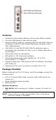
Features • • • • • • • • • Extends the transmission distance of the overall CAN bus system Converts CAN signals to fiber and vice versa Supports CAN (or CAN 2.0, including CAN 2.0A and CAN 2.0B) and its extension CAN FD (CAN Flexible Data Rate); conforms to the ISO 11898 standard CAN (CAN 2.
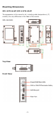
Mounting Dimensions ICF-1171I-S-ST/ICF-1171I-M-ST The appearance is the same for all, including wide-temperature (-T) models; the only difference is the label of the model.
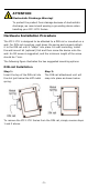
ATTENTION Electrostatic Discharge Warning! To protect the product from damage because of electrostatic discharge, we recommend wearing a grounding device when handling your ICF-1171I Series. Hardware Installation Procedure The ICF-1171I is designed to be attached to a DIN rail or mounted on a wall. For DIN-rail mounting, push down the spring and properly attach it to the DIN rail until it “snaps” into place.
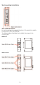
Wall-mounting Installation For wall mounting, the suggested direction of the product is upright— the same as for DIN-rail mounting.
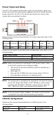
Power Input and Relay The ICF-1171I supports dual power inputs for redundancy. When one power input fails, the relay will be triggered. Be sure to install the dual power inputs for the ICF-1171I Series and choose the correct relay output when connecting the alarm. Please see the terminal block definition for power input and relay in the following table. Relay Relay (Normally (Common) closed) N.C. COM Relay (Normally open) N.O.
Make sure CAN high (CAN_H) is connected to the CAN high pin, and CAN low (CAN_L) is connected to the CAN low pin of your CAN device. Fiber Cable ST-Port Pinouts ST-Port to ST-Port Cable Wiring ATTENTION This is a Class 1 laser/LED product. Do not stare into the laser beam. 1. Caution—Use of the controls or adjustments or the performance of procedures other than those specified herein may result in hazardous radiation exposure." 2. Complies with 21 CFR 1040.10 and1040.
Enable Disable ON OFF (default) There are two rotary switches at the bottom of the ICF-1171I Series, which is used to configure the arbitration rate or data rate of the CAN bus. Rotary switch 1 is used to set up the arbitration rate of CAN (CAN 2.0)/CAN FD (ISO CAN FD); rotary switch 2 is used to set up the data rate of CAN FD (ISO CAN FD). Explore the following use cases to see how you use the rotary switches: Use case 1: My devices use CAN (CAN2.0) with communication speed/bit rate of 1Mbps.
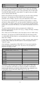
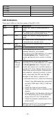
800 kbps 500 kbps 250 kbps Reserved Reserved 5 6 7 8 9 LED Indicators There are 6 LEDs on the front panel of the ICF-1171I.
LED Color Red (Steady) Description The Bus-Off state, or the auto baudrate detection is unsuccessful (Bus-Off state: according to the CAN definition, when the transmit error count exceeds 255, a CAN node will enter the Bus-Off state.) When the LED is steady red, the reception/transmission of CAN messages is not possible. As there are two possible reasons for this condition, check the following to recover: 1.
Typical Scenarios Using the ICF-1171I Connecting two CAN or two CAN FD networks Extending Transmission Distances Typically, the total transmission distance of a CAN (CAN 2.0) or CAN FD (ISO CAN FD) system can be extended by 2 km (multi-mode fiber) or by 40 km (single-mode fiber) using ICF-1171I converters. Note that the ICF-1171I can be connected to another ICF-1171I in a point-to-point connection.
Fiber Communication Connector Type ST (single-mode and multi-mode), 100Base-FX Cable Requirements 9/125 μm (single-mode) or 62.