
Installation Guide
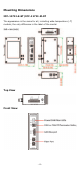
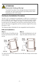

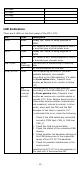
Table Of Contents

- 10 -
800 kbps
5
500 kbps
6
250 kbps
7
Reserved
8
Reserved
9
LED Indicators
There are 6 LEDs on the front panel of the ICF-1171I.
LED
Color
Description
PWR1 Green Steady ON: Power is being supplied to
PWR1
Off
Off: Power is NOT being supplied to PWR1,
or another type of other power error
PWR2
Green
Steady ON: Power is being supplied to
PWR2
Off
Off: Power is NOT being supplied to PWR2,
or another type of power error
CAN TX/RX
Green
(Flashing)
CAN bus port is transmitting or receiving
data
Off
No communication on CAN bus
(CAN) STATE
Green
CAN is operating normally or the auto
baudrate detection is successful
(According to the CAN definition, it’s called
the Error active state; Transmit error
counter or Receive error counter is below
127)
Red
(Flashing
once per
second)
Communication errors have occurred
(According to the CAN definition, it’s called
the Error passive state; Transmit error
counter or receive error counter equals or
exceeds 127). Error Passive becomes Error
Active when communication (transmission
and reception) returns to normal, in other
words, when both the TEC and the REC
decrease to less than or equal to 127.
To eliminate this error, check the following:
1. Check if the CAN cables are connected
correctly (CAN high: CAN_H, CAN low:
CAN_L)
2. Check the CAN bus termination
3. Check the status of the connected CAN
devices
4. Check whether
the baudrate settings of
the CAN devices are in the supported
range of the ICF-1171I’s baudrate
5. Check for possible interferences in the
environment
Resetting the ICF-1171I is not necessary in
this case until it becomes Bus-Off.