
Installation Guide
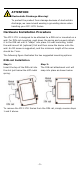
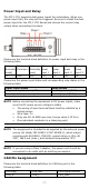

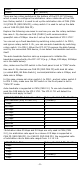
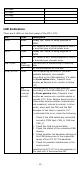
Table Of Contents

- 7 -
Power Input and Relay
The ICF-1171I supports dual power inputs for redundancy. When one
power input fails, the relay will be triggered. Be sure to install the dual
power inputs for the ICF-1171I Series and choose the correct relay
output when connecting the alarm.
Please see the terminal block definition for power input and relay in the
following table.
Relay
(Normally
closed)
Relay
(Common)
Relay
(Normally
open)
DC
Power
input 1
DC
Power
input 1
DC
Power
input 2
DC
Power
input 2
N.C.
COM
N.O.
V1+
V1-
V2+
V2-
Please see the power input status and corresponding relay status in the
following table:
Power input status
Relay status
Both power inputs are on/off
Normally closed (N.C.)
Power input 1 or power input 2 is on
Normally open (N.O.)
NOTE
Before connecting the equipment to DC power inputs, make
sure
the DC power source voltage is stable
•
The wiring of input terminal block shall be installed by a
skilled person.
•
Wire type: Cu
•
Only use 28-14 AWG wire size, torque value 0.19 N-m.
•
One individual conductor in a clamping point.
NOTE
The equipment is intended to be supplied by the external power
source (UL listed/ IEC 60950
-1/ IEC 62368-1), which output
complies with ES1/SELV, PS2/LPS, output rating is
12 to 48
VDC, 188.5 mA (max.), and ambient temperature 75°C
NOTE
If you are
using a Class I adapter, the power cord should be
connected to an outlet with an earthing connection.
CAN Pin Assignment
Please see the terminal block definition for CAN bus port in the
following table.
CAN High
CAN Low
CAN Signal Ground
CAN_H
CAN_L
CAN_GND