Moxa Industrial Media Converter IMC-101G Hardware Installation Guide Second Edition, August 2009 © 2009 Moxa Inc. All rights reserved. Reproduction without permission is prohibited. Fl.4, No.135, Lane 235, Pao-Chiao Rd. Shing Tien City, Taipei, Taiwan, R.O.C.
Overview Moxa’s IMC-101G industrial gigabit media converter is designed for reliable and stable operation in harsh industrial environments, and provides industrial grade media conversion between 10/100/1000BaseT(X) and 1000BaseSX/LX/LHX/ZX connections. The IMC-101G’s reliable industrial design is excellent for keeping your industrial automation applications running continuously, and comes with a relay output warning alarm to help prevent damage.
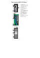
Panel Layouts of IMC-101G Series Top Panel View 1. 2. 1 V2+ PWR2 V2- 2 FAULT V1+ PWR1 V1V1 V2 INPUTS: 24 VDC 3 PORT ALARM 1 ON 2 4 3 DIP Front Panel View 2 5 6 7 8 9 10 1 1000M 0 G2 G2 0 0M G1 G1 3. 4. 5. 6. 7. 8. 9. 10. 11. 12. 13. 14. 15. 16.
Dimensions 46 32.1 6 3. 5 9.75 18.2 30.50 18.00 66.8 25.00 15.00 30.00 50.44 6 M3 M3 63.83 5.00 5.00 86.14 30.50 30.50 25.00 15.00 M3 M3 3. 5 31.90 6 18.2 32.1 46 6 53.00 5 Rear Panel Panel Mounting Kit 15.00 24.79 PWR2 1000M G2 G1 G2 44.00 18.00 134.00 135.00 Industrial Media Converter 9.00 PWR1 FAULT Din-Rail Attachment 100M G1 10M IMC-101-G 105.00 -4- 8.
DIN-Rail Mounting The aluminum DIN-Rail attachment plate should be fixed to the back panel of the IMC-101G when you take it out of the box. If you need to reattach the DIN-Rail attachment plate to the IMC-101G, make sure the stiff metal spring is situated towards the top, as shown in the figures below. STEP 2: STEP 1: Insert the top of the DIN-Rail into the The DIN-Rail attachment unit will slot just below the stiff metal spring. snap into place as shown below.
STEP 2: Mounting the IMC-101G on the wall requires 4 screws. Use the IMC-101G, with wall mount plates attached, as a guide to mark the correct locations of the 4 screws. The heads of the screws should be less than 6.0 mm in diameter, and the shafts should be less than 3.5 mm in diameter, as shown in the figure at the right. 3.5 6.0 mm mm NOTE Test the screw head and shank size by inserting the screw into one of the keyhole shaped apertures of the Wall Mounting Plates, before it is screwed into the wall.
Wiring Requirements WARNING Do not disconnect modules or wires unless power has been switched off or the area is known to be non-hazardous. The devices may only be connected to the supply voltage shown on the type plate. These devices must be supplied by a SELV source as defined in the Low Voltage Directive 2006/95/EC and 2004/108/EC. ATTENTION Safety First! Be sure to disconnect the power cord before installing and/or wiring your Moxa Industrial Media Converter. This equipment is approved by UL508.
ATTENTION This product is intended to be mounted to a well-grounded mounting surface such as a metal panel. Wiring the Alarm Contact The Alarm Contact is made up of the two middle contacts of the terminal block on the IMC-101G’s top panel. Refer to the next section for detailed instructions on how to connect the wires to the terminal block connector, and how to attach the terminal block connector to the terminal block receptor.
ATTENTION Before connecting the IMC-101G to the DC power inputs, make sure the DC power source voltage is stable. Communication Connections All IMC-101G models have one 10/100/1000 BaseT(X) Ethernet port, and one 1000Base SFP Fiber port. 10/100BaseT(X) Ethernet Port Connection The 10/100BaseT(X) ports located on the IMC-101G’s front panel are used to connect to Ethernet-enabled devices.
00BaseT Ethernet Port Connection 1000BaseT data is transmitted on differential TRD+/- signal pairs over copper wires. MDI/MDI-X Port Pinouts Pin 1 2 3 4 5 6 7 8 Signal TRD (0) + TRD (0) TRD (1) + TRD (2) + TRD (2) TRD (1) TRD (3) + TRD (3) - 1 8 1000BaseSFP Fiber Port The gigabit Ethernet ports on the IMC-101G are 1000BaseSFP Fiber ports, which require using gigabit mini-GBIC fiber transceivers to work properly. Moxa provides complete transceiver models for different distance requirements.
Redundant Power Inputs Both power inputs can be connected simultaneously to live DC power sources. If one power source fails, the other live source acts as a backup, and automatically supplies all of the IMC-101G’s power needs. Alarm Contact The IMC-101G has one Alarm Contact located on the top panel. For detailed instructions on how to connect the Alarm Contact power wires to the two middle contacts of the 6-contact terminal block connector, see the “Wiring the Alarm Contact” section above.
LED Indicators The front panel of the IMC-101G has several LED indicators. The function of each LED is described in the table below. LED PWR1 PWR2 FAULT G2 G1 10M 100M Color State Description On Power is being supplied to power input PWR1 Off Power is not being supplied to power input PWR1 On Power is being supplied to power input PWR2 Off Power is not being supplied to power input PWR2 On When the corresponding PORT alarm is enabled, and the port’s link is inactive.
Dual Speed Functionality and Switching The IMC-101G’s 10/100/1000 Mbps RJ45 switched port auto negotiates with the connected device for the fastest data transmission rate supported by both devices. All models of the IMC-101G are plug-and-play devices, so that software configuration is not required at installation, or during maintenance.
Optical Fiber: 1000BaseSX/LX/LHX/ZX Distance Multi mode: Single mode: 1000BaseSX: 0 to 500 m, 850 nm (50/125 µm, 400 MHz*km) 0 to 275 m, 850 nm (62.5/125 µm, 200 MHz*km) 1000BaseLX: 0 to 1100 m, 1310 nm (50/125 µm, 800 MHz*km) 0 to 550 m, 1310 nm (62.5.125 µm, 500 MHz*km) 1000BaseLX: 0 to 10 km, 1310 nm (9/125 µm, 3.5 PS/(nm*km) 1000BaseLHX: 0 to 40 km, 1310 nm (9/125 µm, 3.
Serial Number The serial number of a product is made up of 12 alphanumeric characters and includes the region in which the product was manufactured, the year and month the product was manufactured, the product category, and the production number. Position Meaning in Serial Number Possible Values Example(s) 1 Production 0 to 9, or “T” means Taiwan Region D to Z 2 and 3 Year Z = 0, A = 1, B = 2, ...... I = 9 4 Month A = JAN, B = FEB, C = MAR, ......