Moxa Industrial Media Converter IMC-21 Hardware Installation Guide Second Edition, June 2008 © 2008 Moxa Inc., all rights reserved. Reproduction without permission is prohibited.
Overview The Moxa Industrial Media Converter IMC-21 series consists of entry-level 10/100BaseT(X) to 100BaseFX and 10BaseT to 10BaseFL media converters that provide a cost-effective solution, and are specially designed for reliable and stable operation in harsh industrial environments. IMC-21 accepts either a 12 to 45 VDC or 18 to 30 VAC power input.
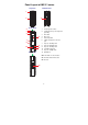
Panel Layout of IMC-21 series Bottom View Top View 1 FX : TP : 2 V+ 3 V24 VDC 24 VAC Dip 1 Dip 3~5 FDX HDX LFP DIS FDX 100 AUTO HDX 10M FORCE Front View 2 4 5 1. Heat dissipation orifices 2. Terminal block for power input and grounding P Tx 6 2 Rx 7 3. DIP switch 4. Moxa Logo 5. Power input LED 6. 100BaseFX (SC/ST connector) 100M port FDX/COL 8 7. FX port’s 100 Mbps LED 8. FX port’s FDX/COL LED 9. TP port’s 100 Mbps LED 100M 10 9 1 10M 11 10.
Panel Layout of IMC-21-M-ST-FL Bottom View Top View 1 2 V+ 4 V24 VDC 24 VAC MDI-X MDI 3 FDX HDX Front View 2 5 6 Heat dissipation orifices 2. Terminal block for power input and grounding P Tx 2 7 Rx 8 LNK/ACT LNK 10 1. 9 1 ACT 11 3. DIP switch 4. Slider switch 5. Moxa Logo 6. Power input LED 7. 10BaseFL (ST connector) port 8. FL port’s LNK/ACT LED 9. TP port’s LNK LED 10. 10BaseT port 11. TP port’s ACT LED 12.
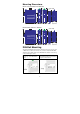
Mounting Dimensions IMC-21 series (10/100BaseTX to 100BaseFX) (unit = mm) 25 P 12 Tx 2 FXȈ TPȈ V+ V- FDX/COL Dip 1 Dip 3~5 FDX HDX LFP DIS FDX HDX 100 24 VDC 24 VAC 74 76.20 109 100M 74 109 109 Rx 10M AUTO FORCE 100M 1 10M 25 73 25 12 Side View 25 Front View Rear View Top View Bottom View IMC-21-M-ST-FL (10BaseT to 10BaseFL) (unit = mm) 25 P 12 Tx 2 MDI-X MDI 74 V+ V- 76.
To remove Moxa IMC-21 from the DIN-Rail, insert a flat-blade screw driver horizontally into the DIN-Rail kit under the IMC-21, and then pull it upwards and release IMC towards you away from the DIN-Rail. Wiring Requirements ATTENTION Safety First! Be sure to disconnect the power cord before installing and/or wiring your Moxa Industrial Media Converter. Calculate the maximum possible current in each power wire and common wire.
Grounding Moxa Industrial Media Converter Grounding and wire routing help limit the effects of noise due to electromagnetic interference (EMI). Run the ground connection from the right most connector of the 3-contact terminal block to the grounding surface prior to connecting devices. ATTENTION This product is intended to be mounted to a well-grounded mounting surface such as a metal panel.
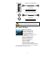
Communication Connections IMC-21 has one 10/100BaseT(X) or 10BaseT Ethernet port. RJ45 Ethernet Port Connection The 10/100BaseT(X) or 10BaseT port located on IMC’s front panel are used to connect to Ethernet-enabled devices. Below we show pinouts for both MDI (NIC-type) and MDI-X (HUB/Switch-type) ports, and also show cable wiring diagrams for straight-through and cross-over Ethernet cables.
SC-Port Pinouts SC-Port to SC-Port Cable Wiring A A B B Tx Cable Wiring Rx A B ST-Port Pinouts A B ST-Port to ST-Port Cable Wiring A A B B Tx Cable Wiring Rx A B A B ATTENTION This is a Class 1 Laser/LED product. To avoid causing serious damage to your eyes, do not stare directly into the Laser Beam.
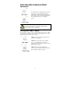
IMC-21-M-ST-FL (10BaseT to 10BaseFL) 1 2 FDX mode ON OFF HDX mode OFF ON ON 1 2 Description TP partner at full duplex mode TP partner at half duplex mode (default) NOTE Only the above two settings for FDX and HDX modes are valid. The switches have no effect on the operation of IMC-21 if DIP switches 1 and 2 are both on, or both off. MDI-X MDI: TP port at MDI mode. MDI-X (Default): TP port at MDI-X mode.
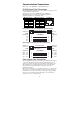
LFP DIP switch is set to “LFP” mode: DUTB DUTA F1 F2 Device2 Device1 TP1 Device1 TP LED TP1 Faulted OFF TP2 DUTA TP DUTA FO DUTB FO DUTB TP Device 2 LNK LED LED LED LNK LED TP LED OFF OFF OFF OFF OFF F1 Faulted OFF OFF OFF OFF OFF F2 Faulted OFF OFF OFF OFF OFF OFF OFF TP2 Faulted OFF OFF OFF OFF OFF OFF LFP DIP switch is set to “DIS” mode: DUTA DUTB F1 F2 Device2 Device1 TP1 Device1 TP LED TP2 DUTA TP DUTA FO DUTB FO DUTB TP Device 2 LNK LED LED LED LNK LED TP LED TP1 Faul
DUTA DUTB F1 F2 Device2 Device1 TP1 Device1 TP LED TP1 Faulted OFF TP2 DUTA TP DUTA FO DUTB FO DUTB TP Device 2 LNK LED LED LED LNK LED TP LED OFF ON OFF ON OFF F1 Faulted ON ON ON OFF ON F2 Faulted OFF ON OFF ON ON OFF ON TP2 Faulted OFF ON OFF ON OFF OFF Auto MDI/MDI-X Connection The Auto MDI/MDI-X function allows users to connect Moxa Industrial Media Converter’s 10/100BaseTX ports to any kind of Ethernet device, without paying attention to the type of Ethernet cable being used
Specifications Technology Standards Interface RJ45 Port Fiber Port LED Indicators DIP Switch IEEE802.3, 802.3u, 802.
Environmental Operating Temperature Storage Temperature Ambient Relative Humidity Regulatory Approvals Safety EMI EMS -10 to 60°C (14 to 140°F) -40 to 70°C (-40 to 158°F) 5 to 95% (non-condensing) UL 508 (pending) FCC Part 15, CISPR (EN55022) class A EN61000-4-2 (ESD), EN61000-4-3 (RS), EN61000-4-4 (EFT), EN61000-4-5 (Surge), EN61000-4-6 (CS), IEC 60068-2-27 IEC 60068-2-32 IEC 60068-2-6 5 years Shock Free Fall Vibration WARRANTY Technical Support Contact Information www.moxa.