
Installation guide


- 11 -
LFP
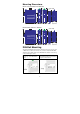
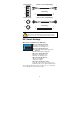
DIP switch is set to “LFP” mode:
Device1
TP LED
DUTA TP
LNK LED
DUTA FO
LED
DUTB FO
LED
DUTB TP
LNK LED
Device 2
TP LED
TP1 Faulted OFF OFF OFF OFF OFF OFF
F1 Faulted OFF OFF OFF OFF OFF OFF
F2 Faulted OFF OFF OFF OFF OFF OFF
TP2 Faulted OFF OFF OFF OFF OFF OFF
LFP
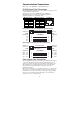
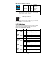
DIP switch is set to “DIS” mode:
Device1
TP LED
DUTA TP
LNK LED
DUTA FO
LED
DUTB FO
LED
DUTB TP
LNK LED
Device 2
TP LED
TP1 Faulted OFF OFF ON ON ON ON
F1 Faulted ON ON OFF OFF ON ON
F2 Faulted ON ON OFF OFF ON ON
TP2 Faulted ON ON ON ON OFF OFF
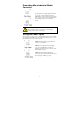
IMC-21-M-ST-FL (10BaseT to 10BaseFL)
LED Color State Description
On Power is being supplied to the power input.
P AMBER
Off
Power is not being supplied to the power
input.
On Fiber port’s link is active.
Blinking Data is being transmitted at Fiber port.
LNK/ACT
(FL)
GREEN
Off Fiber Port’s link is inactive.
On TP port’s link is active.
LNK
(TP)
GREEN
Off TP port’s link is inactive.
ACT
(TP)
GREEN
Blinking Data is being transmitted at TP port.
F1
F2
DUTA
DUTB
TP1
TP2
Device1
Device2
F1
F2
DUTA DUTB
TP1
TP2
Device1
Device2