
Installation guide


- 3 -
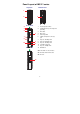
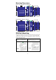
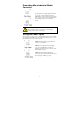
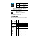
Panel Layout of IMC-21 series
Top View
1
2
Bottom View
24 VAC24 VDC
V+
V-
FDX
FDX
LFP
AUTO
100
FX :
TP :
HDX
HDX
DIS
FORCE
10M
Dip 1
Dip 3~5
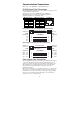
3
Front View
Rear View
2
4
5
7
8
10
6
9
12
11
P
2
Tx
Rx
FDX/COL
100M
10M
1
100M
1. Heat dissipation orifices
2. Terminal block for power input and
grounding
3. DIP switch
4. Moxa Logo
5. Power input LED
6. 100BaseFX (SC/ST connector)
port
7. FX port’s 100 Mbps LED
8. FX port’s FDX/COL LED
9. TP port’s 100 Mbps LED
10. 10/100BaseT(X) port
11. TP port’s 10 Mbps LED
12. DIN-Rail kit
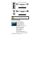
NOTE: The IMC-21 series includes
IMC-21-M-SC, IMC-21-M-ST, and
IMC-21-S-SC.