INJ-24A Series Quick Installation Guide Moxa High-Power PoE+ Injector Edition 4.1, August 2017 Technical Support Contact Information www.moxa.
Overview The Moxa INJ-24A Series high-power PoE+injector is a 1-port PoE+ injector that delivers both data and electrical power to Ethernet-enabled devices using a single Ethernet cable. The INJ-24A can supply up to 36 watts of power in 2-pair mode or 60 watts in 4-pair mode through the Ethernet port, and can power IEEE 802.3af/at compliant powered devices (PD), such as wireless access points or IP cameras, eliminating the need for additional wiring.
WARNING Safety First! Be sure to disconnect the power cord before installing and/or wiring your Moxa PoE injector. Calculate the maximum possible current in each power wire and common wire. Observe all electrical codes dictating the maximum current allowable for each wire size. If the current goes above the maximum ratings, the wiring could overheat, causing serious damage to your equipment.
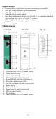
Rugged Design • • • • • • • Active PoE short-circuit and current-overloading protections Auto PoE device detection and classification 3 KV PoE surge resistance Redundant dual power inputs Operating temperature range from 0 to 60°C, or extended operating temperature from -40 to 75°C for “T” models IP30, rugged high-strength case DIN-Rail or panel mounting ability Panel Layout 1. 2. 3. 4. 5. 6. 7. 8. 9. 10. 11. 12. 13.
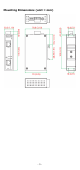
Mounting Dimensions (unit = mm) -5-
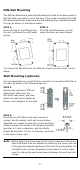
DIN-Rail Mounting The DIN rail attachment plate should already be fixed to the back panel of INJ-24A when you take it out of the box. If you need to reattach the DIN Rail attachment plate, make sure the stiff metal spring is situated towards the top, as shown in the figures below. STEP 1: Insert the top of the DIN rail into the slot just below the stiff metal spring. STEP 2: The DIN rail attachment unit will snap into place as shown below.
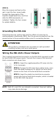
STEP 3: Once the screws are fixed on the wall, insert the four screw heads through the large parts of the keyhole-shaped apertures, and then slide the EDS downwards, as indicated. Tighten the four screws for added stability. Grounding the INJ-24A Grounding and wire routing help limit the effects of noise due to electromagnetic interference (EMI). Run the ground connection from the ground screw to the grounding surface prior to connecting devices.
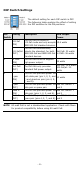
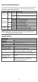
DIP Switch Settings The default setting for each DIP switch is OFF. The following table explains the effect of setting the DIP switches to the ON positions. DIP Setting Switch 1 802.3af (ON) 2 3 4-pair (ON) NOTE Max Output Power The INJ-24A is forced to 802.3af mode and only accepts IEEE 802.3af standard devices. The INJ-24A automatically 802.3af/at detects the standard, for both (OFF) IEEE 802.3af and IEEE 802.3at standard devices. Hi PWR The INJ-24A is set to support (ON) high power output. Std.
Smart PoE LED Indicators Two SmartPoE LEDs indicate the current status between PSE and PD and the power output mode of the INJ-24A. The following table shows the details about these SmartPoE LEDs. LED Description Power is being supplied to power input P1 ON /P2 P1, P2 Amber Power is not being supplied to power input OFF P1 / P2 ON 802.3at connection Green Blinking PoE current overloading OFF No PoE power output 802.3af/at (SmartPoE) ON 802.
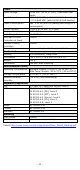
Power Input Voltage Input Current Power Consumption Inrush Current Electrical Isolation Heat Dissipation Overload Current Protection at Input Reverse Polarity Protection Connection Mechanical Housing Dimensions Weight Installation Environmental Limits Operating Temperature 24/48 VDC (22 to 57 VDC), redundant dual inputs 2.71 A @24 VDC (with full 60 W PoE loading) 1.37 A @48 VDC (with full 60 W PoE loading) Max. 5.29 W (with full loading excluding PD’s consumption) 15.64 A @ 48 VDC (0.