
User Manual

- 7 -
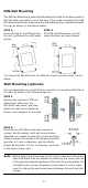
STEP 3:
Once the screws are fixed on the
wall, insert the four screw heads
through the large parts of the
keyhole
-
shaped apertures, and then
slide the EDS downwards, as
indicated. Tighten the four screws
for added
stability.
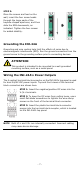
Grounding the INJ-24A
Grounding and wire routing help limit the effects of noise due to
electromagnetic interference (EMI). Run the ground connection from the
ground screw to the grounding surface prior to connecting devices.
ATTENTION
This product is intended to be mounted to a well
-grounded
mounting surface, such as a metal panel.
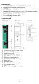
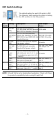
Wiring the INJ-24A’s Power Outputs
The 4-contact terminal block connector on the INJ-24A’s top panel is used
for dual 24/48 VDC power inputs. Top and front views of the terminal
block connectors are shown here.
STEP 1:
Insert the negative/positive DC wires into the
V
-/V+ terminals.
STEP 2:
To keep the DC wires from pulling loose, use a
small flat
-blade screwdriver to tighten the wire-clamp
screws on the front of the terminal block connector.
STEP 3:
Insert the plastic terminal block connector
prongs into the terminal block receptor, which is located
on
the INJ-24A’s top panel.
NOTE
Both V1+ and V2+ are internally connected. Incorrect cabling
may cause device damage.