
User Manual

- 9 -
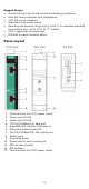
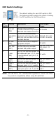
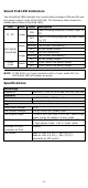
Smart PoE LED Indicators
Two SmartPoE LEDs indicate the current status between PSE and PD and
the power output mode of the INJ-24A. The following table shows the
details about these SmartPoE LEDs.
LED
Color
State
Description
P1, P2 Amber
ON
Power is being supplied to power input P1
/P2
OFF
Power is not being supplied to power input
P1 / P2
802.3af/at
(SmartPoE)
Green
ON
802.3at connection
Blinking
PoE current overloading
OFF
No PoE power output
Amber
ON
802.3af connection
Blinking
PoE current overloading
OFF
No PoE power output
4-pair
mode
Green
ON
4-pair mode PoE power output
OFF
2-pair mode PoE power output
NOTE
If INJ-24A is in 4-pair mode but with a 2-pair mode PD, the
802.3af/at LED will always be green.
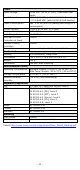
Specifications
Technology
Standards
IEEE 802.3, 802.3u, 802.3ab, 802.3af, 802.3at
Interface
RJ45 Ports
10/100/1000BaseT(X) speed
LED Indicators
P1, P2, 802.3af/at, 4-pair mode
PoE
Total Power Budget
60 W
PoE Output Voltage
50V @ 24/48 VDC power input
PoE Output Power
15.4W in 802.3af, 30W in 802.3at, 36W in high
power mode, 60 watts in 4-pair mode
PoE Output Current
350 mA in 802.3af, 600 mA in 802.3at, 720 mA
in high power mode, 1.2A in 4-pair mode
Overload Current
Protection at Port
Present
PoE Pinout
Mode A: Pair 1,2 (V+) ; Pair 3,6 (V-)
Mode B: Pair 4,5 (V+) ; Pair 7,8 (V-)
selectable by DIP switch