ioLogik Cellular Micro RTU Controller User’s Manual Seventh Edition, June 2012 www.moxa.com/product © 2012 Moxa Inc. All rights reserved.
ioLogik Cellular Micro RTU Controller User’s Manual The software described in this manual is furnished under a license agreement and may be used only in accordance with the terms of that agreement. Copyright Notice © 2012 Moxa Inc., All rights reserved. Trademarks The MOXA logo is a registered trademark of Moxa Inc. All other trademarks or registered marks in this manual belong to their respective manufacturers.
Table of Contents 1. Introduction ...................................................................................................................................... 1-1 Quick Start Guide ............................................................................................................................... 1-2 Architecture .......................................................................................................................................
Timer Settings .......................................................................................................................... 4-10 SNMP Trap Server...................................................................................................................... 4-11 E-Mail Server ............................................................................................................................ 4-11 Active Message Server ...............................................................
G. FAQ ...................................................................................................................................................
1 1. Introduction Moxa’s ioLogik Cellular Micro RTU Controllers are highly integrated, stand-alone solutions designed for remote monitoring applications, and are especially well suited for cellular communications. Using push technology and Active OPC server solves the problems associated with using dynamic IP addresses in cellular communications.
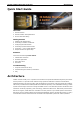
ioLogik Cellular Micro RTU Controller Introduction Quick Start Guide Overview 1. Product Features 2. Product Selection and Specifications 3. Pin-outs and Cable Wiring Getting Started 1. Installing the ioAdmin Utility 2. Connecting to ioAdmin via Ethernet 3. Configuring the DIO Channels 4. Connecting I/O Devices and Sensors 5. Connecting … over a Cellular Network 6. Sample Scenarios for Quick Setup Software Learn about the following useful utilities. 1. ioAdmin Basic Functions 2.
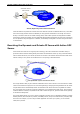
ioLogik Cellular Micro RTU Controller Introduction Active OPC Server with Fixed IP Internet GPRS/EDGE/3G/ HSDPA Network Host Actively Registering with an Active OPC Server Unlike the static IP requirements of remote devices for Ethernet I/O with a traditional OPC server, Active OPC Server and ioLogik products deliver the flexibility of using dynamic IP addresses.
ioLogik Cellular Micro RTU Controller Introduction Active OPC Server and ioLogik W5300 series products offer “Auto Tag Generation” to eliminate the headache of specifying target IP addresses, I/O channels, and data formats one by one or editing and importing configuration text files. Instead, Active OPC Server creates the tags for the target ioLogik automatically. All you need to do is select the channels to be updated to Active OPC Server.
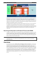
ioLogik Cellular Micro RTU Controller Introduction with with with with Cellular Communication Front-end Intelligence Front-end Data Logging Serial Tunnel Product Features • Trouble-free connections to cellular networks • Automatic data update from SD cards following network failure • Front-end intelligence for event handling • Intelligent SMS alarms and SMS commands • Friendly serial device connectivity • Network redundancy • WAN-to-LAN extension with port forwarding • Secure wake o
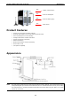
ioLogik Cellular Micro RTU Controller Introduction LED Indicators Function Description Mark Power Input OFF: No Power PWR Cellular Status OFF: Cellular Disconnected or in “On Demand” Mode Green: Power On GPRS or LINK Amber: Cellular Connected at “Always ON” Blinking: Connected with Active OPC Server System Status Green: System Ready READY Ready LED is blinking and Fault LED is not lit: Click&Go is running Ready LED is blinking and Fault LED is blinking: Safe Mode Communication Activity OFF: No
ioLogik Cellular Micro RTU Controller Introduction • 5-pin screw terminal block x 1 (for RS-485) • Documentation and software CD • Antenna NOTE: Notify your sales representative if any of the above items are missing or damaged. Product Selection Guide The Cellular Micro RTU Controller product family includes the ioLogik W5340, ioLogik W5340-T, and ioLogik W5312, as described in the following table. Model I/O Combination Operating Temp.
ioLogik Cellular Micro RTU Controller Introduction SIM Control Voltage: 3 V LAN Ethernet: 1 x 10/100 Mbps, RJ45 Protection: 1.
ioLogik Cellular Micro RTU Controller Introduction ioLogik W5312/W5312-T Specifications Inputs and Outputs Digital Inputs: 8 channels Digital Outputs: 8 channels Configurable DIOs: 4 channels Isolation: 3K VDC or 2K Vrms Digital Input Sensor Type: Wet Contact (NPN or PNP) and Dry Contact I/O Mode: DI or Event Counter Dry Contact: • On: short to GND • Off: open Wet Contact (DI to GND): • On: 0 to 3 VDC • Off: 10 to 30 VDC Common Type: 6 points per COM Counter Frequency: 900 Hz, power off storage Digital F
ioLogik Cellular Micro RTU Controller Introduction Accuracy: • ±0.1% FSR @ 25°C • ±0.3% FSR @ -30 and 70°C Sampling Rate: W5340: • All channels: 25 samples/sec • Per channel: 6.25 samples/sec • Only one channel enabled: 100 samples/sec Input Impedance: 200K ohms (min.
ioLogik Cellular Micro RTU Controller Introduction Time: ioLogik W5340: 196,561 hrs ioLogik W5340-HSDPA/W5348-HSDPA-C: 280,739 hrs Database: Telcordia (Bellcore) 1-11
2 2. Getting Started This chapter describes how to install the ioLogik W5300.
ioLogik Cellular Micro RTU Controller Getting Started Cellular Micro RTU Controller Flowchart ioAdmin Utility Installation Laboratory Test System Planning Other Software Installation See Chapter 3 See Chapter 4, 6, 7 ioLogik Configuration See Chapter 4 Click&Go Programming See Chapter 5 Field Site Deployment Before Testing Prepare the following items before testing the ioLogik W5300. 1. Set up the Active OPC server environment, including network settings. 2.
ioLogik Cellular Micro RTU Controller Getting Started Laboratory Testing Grounding the Unit The ioLogik is equipped with one grounding point located on the top of the device next to the Power Input Terminal Block. To provide better stability for both power and signal transmission, we recommend wiring the grounding point to a suitable grounded contact, such as the power supply or a cabinet enclosure. Connecting the Power Connect the 12 to 36 VDC power line to the ioLogik’s Power Input Terminal Block.
ioLogik Cellular Micro RTU Controller Getting Started Connecting to ioAdmin via Ethernet Configuring the Computer’s IP Address 1. For initial configuration, we recommend using a direct connection through the RJ45 Ethernet console port to a host computer, rather than remotely over the cellular network. Connect the ioLogik to the host PC with an Ethernet cable. 2. Set the host PC’s IP address to 192.168.127.xxx. (where xxx can range from 001 to 253).
ioLogik Cellular Micro RTU Controller Getting Started 3. if the host computer has multiple interfaces, be sure to select the correct one before searching. NOTE If multiple ioLogik W5300 units with same default IP address are installed on the same network, you will need to assign a different IP address to each unit to avoid IP conflicts. ioAdmin automatically detects IP conflicts and gives you a chance to modify each unit’s IP address in the IP Address column.
ioLogik Cellular Micro RTU Controller Getting Started 5. Monitoring and Testing I/O status: Once your unit has been found by ioAdmin, you can view the status of all attached I/O on ioAdmin’s main screen. NOTE ioAdmin supports four viewing options for the navigation panel. If you select “sort by Active OPC server,” the ioLogik W5300 will appear in the Active OPC server group.
ioLogik Cellular Micro RTU Controller Getting Started Configuring the DIO Channels The ioLogik W5300 product family is equipped with different I/O types, including analog inputs, digital inputs, digital outputs, relay outputs, and software configurable DIOs, offering great flexibility for connecting I/O devices such as software configurable DIO channels. Before you connect I/O devices and sensors, you should configure the DIO channels as DI or DO.
ioLogik Cellular Micro RTU Controller Getting Started Digital Input Wet Contact (Connect to NPN-type Sensor) Digital Input Wet Contact (Connect to PNP-type Sensor) Digital Output (Sink Type) Relay Output 2-8
ioLogik Cellular Micro RTU Controller Getting Started ATTENTION When connecting the I/O device to the ioLogik’s dry contacts, we strongly recommended connecting DI.Com to the power of the external sensor to avoid affecting other channels. DI.Com input power should be limited at 12 to 36 VDC. ATTENTION Sensor types are arranged in groups, with DIO-0 to DIO-3 forming one group and DIO-4 to DIO-7 forming another group.
ioLogik Cellular Micro RTU Controller Getting Started DIN Rail / Wall Mounting The ioLogik W5300’s built-in mounting appendages are suitable for mounting on a flat wall or installing on a DIN rail. Follow the instructions in the figures below to install the W5300 on a DIN rail. STEP 1: Insert the top of the DIN rail into the slot. STEP 2: The DIN rail attachment unit will snap into place as shown below.
ioLogik Cellular Micro RTU Controller Getting Started Installing/Removing the SIM Card and SD Card The ioLogik is equipped with two slots; one is for SIM cards and the other is for SD cards. The card reader slots are protected inside the ioLogik device. You will need to unscrew and remove the card cover to install your SIM and SD cards. When inserting a SIM card or SD card, remember to keep the front edge of the card facing down. Follow these steps to remove or install a SIM or SD card: 1.
ioLogik Cellular Micro RTU Controller Getting Started Connecting the Cellular Micro RTU Controllers over a Cellular Network When the environment is ready, follow these steps to test the ioLogik W5300 (refer to the figure below). Step 1: Connect directly from the PC to the W5300 and use ioAdmin to configure the W5300’s cellular settings. Step 2: For the ioLogik W5300, enter the user name, password, SIM Pin, APN, and define the Active OPC server IP on the cellular settings page.
ioLogik Cellular Micro RTU Controller Getting Started Detailed instructions: 1. Power off the ioLogik W5300. 2. Insert a SIM card that can connect to the cellular network. 3. Connect to ioAdmin via the Ethernet port of the ioLogik. 4. Power on the ioLogik and start ioAdmin. 5. After connecting ioAdmin and the ioLogik W5300, log in with the administrator password. 6.
ioLogik Cellular Micro RTU Controller Getting Started Installing Active OPC Server on a Host that has a Public Static IP Address Moxa’s Active OPC Server™ is a software package operating as an OPC driver of an HMI or SCADA system. It seamlessly connects Moxa’s ioLogik products to a wide variety of SCADA systems, including the most popular: Wonderware, Citect, and iFix. Active OPC Server™ conforms to the OPC Foundation’s latest data access standard, DA 3.
ioLogik Cellular Micro RTU Controller Getting Started Import/Export Configuration File Using ioAdmin to Import/Export the Configuration To import or export a system configuration right click on the I/O model name and then selection Import System Config or Export System Config. You must be logged in as an administrator to use this command. Export System Config Select this command to export the selected ioLogik’s configuration to a text file.
3 3. Utility: ioAdmin In this chapter, we explain how to use ioAdmin to configure your ioLogik product.
ioLogik Cellular Micro RTU Controller Utility: ioAdmin ioAdmin System Requirements ioLogik Cellular Micro RTU Controllers can be managed and configured over the Ethernet or Cellular network with ioAdmin, a Windows utility provided with your ioLogik. ioAdmin’s graphical user interface gives you easy access to all status information and settings. ioAdmin can also be used to configure Click&Go rules to provide front-end event handling capabilities.
ioLogik Cellular Micro RTU Controller Utility: ioAdmin ioAdmin Basic Functions Main Screen Overview This is ioAdmin’s main screen. The main window defaults to the I/O Configuration panel, which displays a figure of your unit with the status of every I/O channel. The other tabs in the main window take you to device and network settings, and further functions are available when you log onto the ioLogik. Note that configuration options are not available until you log in as administrator. 1. Title 2.
ioLogik Cellular Micro RTU Controller Utility: ioAdmin When importing/exporting a device list, you will be prompted to select which ioLogik on the list needs to be imported or exported. When a popup window appears, click the “folder” icon to select/key-in the file name to save/import a specific file. The file will have an .SLT extension and can be opened as a text file. The server list will provide the basic information for each server, such as Device Name, Model, IP address, and Unit ID.
ioLogik Cellular Micro RTU Controller Utility: ioAdmin Click Start Search to start searching. Network Interface allows you to select a network to use (if the PC has multiple network adaptors installed). The default network interface will be the same as the Windows’ setting. Make sure the interface is correct when connecting to the ioLogik device; otherwise, no devices will be found. I/O Status Refresh Rate is used to adjust how often the ioLogik is polled for device status by the ioAdmin utility.
ioLogik Cellular Micro RTU Controller Utility: ioAdmin COM Port Setting is used to set the default parameters for the ioAdmin utility to establish a Modbus connection, such as baudrate, data bits, and timeout interval. For most applications, this will involve connecting to ioLogik R-series devices. Active Message Listen Port specifies the port number to use for Active Messages.
ioLogik Cellular Micro RTU Controller Utility: ioAdmin Menu Bar: Sort The Sort menu allows the Devices list in the navigation panel to be sorted by connection, model, location, or Active OPC. Quick Links Quick links are a collection of commonly used functions, including the search and the sort function. Search the network for ioLogik devices “Auto Scan ioLogik devices” allows users to search and locate an ioLogik on the same physical network, or specify a remote IP address to connect to a remote ioLogik.
ioLogik Cellular Micro RTU Controller Utility: ioAdmin Menu Bar: Help ioAdmin provides a wiring guide for the ioLogik W5300 series. You can access the wiring guide by right-clicking the ioLogik figure in the I/O Configuration panel, or select “Wiring Guide” in the submenu to open a help file showing the unit’s wiring information and electrical characteristics. You can also access the On-line Wiring Guide through the Help menu on the menu bar.
ioLogik Cellular Micro RTU Controller Utility: ioAdmin Navigation Panel A function menu is accessed by right clicking on the server model name in the navigation panel. The menu lists both basic functions and advanced functions: Basic Functions: Add, Connect, and Disconnect Add ioLogik ioLogik device: Select ioLogik tag and right click the tag. Select the “Add ioLogik device” command to add an ioLogik device or Active OPC server manually.
ioLogik Cellular Micro RTU Controller Utility: ioAdmin Main Window The Main Window allows users to view the I/O status, ioLogik system information, and check the Message Monitor, without needing to log in to the ioLogik. However, you will need to log in to perform configuration and operation tasks. I/O Configuration Panel (General) The I/O Configuration panel shows the status of every I/O channel. This is the default panel when you first open ioAdmin.
ioLogik Cellular Micro RTU Controller Utility: ioAdmin Message Monitor Panel (General) The Message Monitor panel will display any TCP/UDP Active Messages reported by the ioLogik W5300. When you install the unit for the first time, the ruleset will not have been defined yet, so there will be no messages on the Message Monitor Panel. When a ruleset has been defined and activated, any TCP/UDP messages that have been triggered by sensor events will be shown on the Message Monitor panel.
ioLogik Cellular Micro RTU Controller Utility: ioAdmin ioAdmin Administrator Functions For full access to all configuration options, log in as administrator from the Server Settings panel. This is required whenever you start up ioAdmin or boot up or restart the ioLogik. When you install the ioLogik for the first time, the password will be blank; in this case, just click Login.
ioLogik Cellular Micro RTU Controller NOTE Utility: ioAdmin The server also relates to the node created in the Active OPC Server. LAN Settings Panel The LAN Settings panel is available after you log in as administrator. You will be able to configure IP settings, Modbus/TCP Alive Check Timeout settings, DNS settings, and SNMP settings. IP Settings You can set up a static or dynamic IP address for the ioLogik, as well as the subnet mask and gateway address.
ioLogik Cellular Micro RTU Controller Utility: ioAdmin DNS Settings Use this field to specify the IP addresses of one or two DNS servers. DNS servers can be used to find available e-mail addresses when setting up Click&Go rules. (By default the DNS setting is set to automatic. If you want to configure a specific setting, contact your local cellular provider for details.
ioLogik Cellular Micro RTU Controller Utility: ioAdmin Users can disable the unused AI channel by un-checking the Enable checkbox to increase the sampling rate.
ioLogik Cellular Micro RTU Controller Utility: ioAdmin The Reset Min and Reset Max buttons will clear the minimum or maximum values recorded and displayed in the ioAdmin main window. Configuring Virtual Channels The ioLogik W5300 has 10 internal virtual channels to support front-end statistics functions, such as Max, Min, Average, Accumulation, Instantaneous, and Incremental.
ioLogik Cellular Micro RTU Controller Display in ioAdmin Utility: ioAdmin Update to AOPC Use Virtual Channel to get the value, such as Max, Min, Average, Accumulation, Instantaneous, and Incremental Convert to New Unit by Scaling functions. (This step can be skipped.) AI Data Counter Value After double-clicking on a virtual channel a popup window will appear (see below). First select the physical source I/O. There are three types: AI, Counter, and I/Os from expansion modules.
ioLogik Cellular Micro RTU Controller Utility: ioAdmin Configuring DIO Channels Channels DIO-0 to DIO-7 support both DI and DO channel operations. When the ioLogik W5300 is turned on, each DIO channel will be configured to act as either a DI or DO channel, according to the Power On Settings. To switch between DI and DO channel operation, select the desired mode in the I/O Direction field under Power On Settings.
ioLogik Cellular Micro RTU Controller Utility: ioAdmin Type Logic 0 Logic 1 Dry contact Close to GND open Wet contact 0 to 3 V 10 to 30 V In Event Counter mode, the channel accepts limit or proximity switches and counts events according to the ON/OFF status. When “Lo to Hi” is selected, the counter value increases when the attached switch is pushed. When “Hi to Lo” is selected, the counter value increases when the switch is pushed and released.
ioLogik Cellular Micro RTU Controller Utility: ioAdmin By default, the Event Counter value will be reset to zero if power is disconnected. If you select Save status on power failure, the Event Counter value will be saved when power is disconnected. When power is reconnected, the value will be as you left it. You can set Power On Settings to resume counting immediately. The Event Counter starts counting events when specified by a Modbus command or a Click&Go Logic rule.
ioLogik Cellular Micro RTU Controller Utility: ioAdmin In DO mode, the specifications are as follows. Type Logic 0 (OFF) Logic 1 (ON) DO mode open short In Pulse Output mode, the selected digital output channel will generate a square wave as specified in the pulse mode parameters. The low and high level widths are specified in multiples of 0.5 ms for Digital Output (1.5 s for Relay output), with a maximum setting of 65,535. For digital output, you would enter 1000 for a width of 500 ms.
ioLogik Cellular Micro RTU Controller Utility: ioAdmin You can control how a DO/Relay output channel acts when the network is disconnected by using the Safe Status Settings and the Host Connection Watchdog. When the Host Connection Watchdog is enabled, a network disconnection will activate the Safe Status Settings. The DO channel can be configured to turn on, turn off, or commence pulse output.
ioLogik Cellular Micro RTU Controller Utility: ioAdmin Alias Name Alias Name helps users configure the alias of a DI or DO/Relay Output channel and define the status for On/Off to be Open/Close or vice versa. The Alias can be monitored by the ioAdmin utility, or can be queried using a user-defined program based on the Moxa MXIO library, or a standard TCP/Modbus protocol. I/O Expansion Panel The ioLogik W5300 allows you to install Three additional ioLogik E1200 I/O expansion modules.
ioLogik Cellular Micro RTU Controller Utility: ioAdmin ATTENTION The expansion module should be installed on the same network segment or the ioLogik W5300 will not be able to detect it. This is the only limitation. You do not need to connect them directly, and they can also be connected through the network switch. • The sequence is indicated in the Slot# column. • To activate the function, restart the ioLogik W5300 after adding expansion modules.
ioLogik Cellular Micro RTU Controller Utility: ioAdmin The W5300 micro controller allows you to connect the first expansion module with an Ethernet cable through the RJ45 port, and daisy chain to the second and third expansion modules using the E1200’s embedded Ethernet switch ports. Step 4: Restart the ioLogik W5300. Use the last E1200 module’s RJ45 port to connect to the Host PC and then restart the ioLogik W5300. Open ioAdmin and log in.
ioLogik Cellular Micro RTU Controller Utility: ioAdmin Active Tags Panel When logged in as administrator, fill in the fixed IP address on the Active Tags panel to configure the Active OPC Address and Port settings. The Active OPC Server Address can be filled in using the IP or DNS format. The default port number is 9900. The port number should be the same as the setting in Active OPC Server’s “Active Tag Listen Port.” After the OPC setting and Channel Tags have been configured, click Create Tags.
ioLogik Cellular Micro RTU Controller Utility: ioAdmin Active OPC: Redundancy Mode Active Tag offers three Active OPC redundancy Modes: Normal, Synchronicity, and Change while failed. Normal Active OPC Connects with Active OPC Servers 1 Synchronicity and 2 at the same time. Tries to connect with the first Active OPC Server IP.
ioLogik Cellular Micro RTU Controller Utility: ioAdmin Read/Write Privilege An input channel can only be read while an output channel is shown as read/write acceptable in Active OPC Server. Note that a channel is read only if an output channel was used in the Click&Go logic tag of that channel. Active Tags A tag selection table shown in the right panel of the browser window shows the details of your selection.
ioLogik Cellular Micro RTU Controller Utility: ioAdmin NOTE: 1. The Virtual Channel is updated periodically, the time interval unit can be set to sec, min, hour, or day, with values ranging from 1 to 65535. 2. If AI is configured to update on change, the percentage settings represents the percentage of the full analog range. For example, if the AI is configured to 0 to 10V, On Change 1% means the ioLogik will update the Active OPC Server every time there is 0.1V change. 3.
ioLogik Cellular Micro RTU Controller Utility: ioAdmin Cellular Settings Panel The Cellular Setting includes Dial-up Setting, Caller IDs, Operation Mode, DDNS Setting, and Port Forwarding Setting. Dial-up Setting *APN is a very important factor when connecting to a Cellular network. Check with your Cellular service provider for details. If you already have a SIM PIN, make sure it is correct because you will be locked out after three failed attempts.
ioLogik Cellular Micro RTU Controller Utility: ioAdmin must reboot in order for the settings to take effect. Connection information is displayed on the right side of the block, such as Signal Strength (RSSI), Cellular Status which includes the device’s IP address for the Cellular Network, and Cellular Error. Caller IDs In order to wake up the ioLogik W5300, the caller ID setting must be configured. When the ioLogik W5300 is in Sleep Mode, it switches to GSM standby mode.
ioLogik Cellular Micro RTU Controller Utility: ioAdmin DDNS Settings If your cellular service provider offers a public IP address after you connect to the cellular network, you can also access the ioLogik W5300 micro RTU controllers using the domain name. To do this, you will need to register with a DDNS service provider and then enable the DDNS function in the ioLogik 5300. The purpose of DDNS is to provide the customer with an alternative cost effective cellular plan.
ioLogik Cellular Micro RTU Controller NOTE Utility: ioAdmin Currently, the ioLogik W5300 supports DNS service as provided by DynDNS. For detailed information on this option, please visit https://www.dyndns.com. Port Forwarding With the 3G antenna and RJ45 connector the cellular W5300 RTU supports port forwarding technology that enables WAN-to-LAN communication with port redirection settings.
ioLogik Cellular Micro RTU Controller Utility: ioAdmin Example: Gateway to gateway connection between ioLogik and IPSec servers ioAdmin VPN Settings Tab General Settings VPN Tunnel Mode: Manual Key/ESP or ISAKMP/PSK selection Remote Endpoint IP: Enter the WAN IP of the remote VPN server endpoint Remote Subnet IP: Enter the remote VPN server subnet (LAN) IP of the remote network Remote Subnet netmask: Enter the remote VPN server subnet netmask of the remote network Local subnet IP: Enter the ioLogik W530
ioLogik Cellular Micro RTU Controller Utility: ioAdmin Manual Key/ESP SPI: Sets the VPN manual key incoming/outgoing SPI between 257 and 4294967295 Encryption mode: Selects the incoming/outgoing encryption mode Encryption key: Enters the incoming/outgoing encryption key Encryption mode Length (Bytes) DES 8 3DES 24 AES 128bit 16 AES 192bit 24 AES 256bit 32 Authentication mode: Select the incoming/outgoing authentication mode Authentication key: Enter the incoming/outgoing authentication key Au
ioLogik Cellular Micro RTU Controller Utility: ioAdmin ISAKMP/PSK Local Identify Pre-Share Key (PSK): Sets the VPN ISAKMP Pre-Shared key settings Perfect forward secrecy (PFS): Enable or disable Perfect Forward Secrecy.
ioLogik Cellular Micro RTU Controller Utility: ioAdmin ISAKMP phase 2 Encryption mode: Select the VPN ISAKMP phase 2 encryption mode. Authentication mode: Select the VPN ISAKMP phase 2 authentication mode. Diffie-Hellman group: Select the VPN ISAKMP phase 2 DH group. Increasing the DH Group number increases the level of encryption implemented for PFS.
ioLogik Cellular Micro RTU Controller NOTE Utility: ioAdmin The default setting of the Cellular Reconnection function is disabled, which prevents it from producing extra packets. If the Cellular Operation Mode is set to On-Demand, we recommended NOT activating the Cellular Reconnection function. Carrier Check before system restart: Carrier Check settings define the timeout for detecting the physical cellular connection. Once the ioLogik reaches the timeout, it will perform a system restart.
ioLogik Cellular Micro RTU Controller Utility: ioAdmin PING Check before system restart: A remote destination is used in this setting to indicate if the Internet connection is still alive. The user can specify a public IP or URL and the number of retries that are allowed. • Dest IP/URL: Can either be an AOPC server IP or any public URL for the device to check its connection with the internet. • Auto Retry: Will be activated when the AOPC can’t connect with the AOPC server.
ioLogik Cellular Micro RTU Controller Utility: ioAdmin ATTENTION If the Serial Tunnel setting is used, Cellular Setting Operation Mode Cellular should be set to “Cellular Always On.” Otherwise, the Cellular connection will disconnect and a serial tunnel will not be created. ATTENTION Because there are major structural differences between firmware versions, you should upgrade from earlier versions to firmware V1.3 or above for the ioLogik W5312 series, V1.
ioLogik Cellular Micro RTU Controller Utility: ioAdmin Watchdog Panel The Watchdog panel is available after you log in as administrator. When enabled, the Host Connection Watchdog monitors the network connection. If the connection is lost for the specified Timeout value, the Watchdog will display a warning and activate the Safe Status settings for each DO channel and Event Counter channel. By default, the Watchdog is disabled.
ioLogik Cellular Micro RTU Controller Utility: ioAdmin Changes on the Click&Go Logic panel are not effective until the ioLogik W5300 is restarted, as is true with changes made on other panels. After logging back in as administrator and returning to the Click&Go Logic panel, click Download to view the current ruleset. Click Run to activate the ruleset and Stop to deactivate it. NOTE Refer to the following website to learn more about Click&Go: http://www.moxa.com/remote_io/ClicknGo.
4 4. Click&Go Logic Click&Go Logic was developed by Moxa to provide an easy way to program your ioLogik W5300 product for Cellular Micro RTU Controller operation. In this chapter, we explain how Click&Go Logic works and how to use it to develop your Cellular Micro RTU Controller.
ioLogik Cellular Micro RTU Controller Click&Go Logic Quick Start Guide Overview • Software Overview • Utility Features • Working with the Rules Getting Started Quickly set up your I/O and global variables so you can start working with rules: • I/O configuration • Defining Global Varibles Start Working with Logic Learn the basics of Click&Go’s If-Then-Else Logic: • If Logic • Then and Else Logic • Active Rule Set • Import and Export Your Configuration 4-2
ioLogik Cellular Micro RTU Controller Click&Go Logic Overview The ioLogik W5300 series system eliminates the need for host computers to continually poll I/O devices for their status. Instead, the server itself is able to monitor the status of each I/O device and take the appropriate action when the I/O status satisfies a user-defined condition. For example, the ioLogik could be configured to send a TCP/UDP message only when the switch attached to DI-0 is turned on.
ioLogik Cellular Micro RTU Controller Click&Go Logic Click&Go Logic Basics To use Click&Go Logic, start ioAdmin and log on as an ioLogik administrator on the Server Settings panel. Once you are logged on, go to the Click&Go Logic panel. It should appear as below: Click&Go Logic Panel 1. Global Variable: In this field, you can assign a Global Variable for the set of rules. 2. Logic Name: In this field, you can assign a name for the set of rules. 3.
ioLogik Cellular Micro RTU Controller Click&Go Logic Working with Rules Rules are the building blocks of your ioLogik Cellular Micro RTU Controller. With rules, you define the exact trigger conditions for transmission of I/O information as well as the content and destination of that information. A DO’s reaction can also be automated through DI trigger conditions. In the main screen, you will see a list of the rules in the current rule set.
ioLogik Cellular Micro RTU Controller Click&Go Logic I/O Configuration ioLogik products are embedded with various types of I/O channels, and the mode of each input/output channel must be configured before using the channels. Channels are divided into five categories: digital inputs, digital outputs, analog inputs, analog outputs, and virtual channels.
ioLogik Cellular Micro RTU Controller Click&Go Logic ATTENTION On this panel, be sure to select Start under Counter mode parameter on Power On Settings to activate the Event Counter channel. Digital Output Mode Selection A DO channel can be set to DO or Pulse Output mode. The Relay Output behavior is the same as DO.
ioLogik Cellular Micro RTU Controller Click&Go Logic Analog Input Mode Selection Analog input channels can use either voltage or current to transmit signals. ioLogik W5340-HSDPA Mode Selection Number of Analog Model Input Channels 4 Voltage ±5 V, ±10 V, 0-10 V ioLogik W5340 Current 0 to 20 mA, 4 to 20 mA When logged in as administrator, double click on a channel on the I/O Configuration panel to configure that channel’s settings. A window will open with configuration options for that channel.
ioLogik Cellular Micro RTU Controller Click&Go Logic ATTENTION We strongly recommend configuring the alias name for the I/O channel being used before performing any further configuration or programming. Testing the I/O Channels Each I/O channel can be tested and monitored individually. When logged in as administrator, double click on a channel from the I/O Configuration panel to configure that channel’s settings. A window will open with configuration options for the channel.
ioLogik Cellular Micro RTU Controller Click&Go Logic Defining Global Variables Global Variables include Internal Register Settings, Timer Settings, SNMP Trap Server, E-Mail Server, Active Message Server and SMS Phone Book. If these functions will be used in a Click&Go V2 rule-set, the default configuration must first be set from the Global Variable Menu Bar.
ioLogik Cellular Micro RTU Controller Timer Click&Go Logic Timer Number Initial State Configuration Timer-0 to Timer-23 START, *STOP SNMP Trap Server The ioLogik W5300 supports SNMP v2 (Simple Network Management Protocol) to allow monitoring of the network and I/O devices with SNMP Network Management software. It is useful for building automation and telecom applications.
ioLogik Cellular Micro RTU Controller Click&Go Logic Under Mail Server Settings, you must configure the address of the SMTP server with your username and password. When using an FQDN (Fully Qualified Domain Name) address, such as ms.moxa.com, you must specify the ioLogik’s DNS settings or check the Cellular Settings to see if the DNS settings were retrieved by the cellular connection.
ioLogik Cellular Micro RTU Controller Click&Go Logic Active Message Server The Active Message Server configures one or more destination IP addresses of the Message Servers that receive event messages generated by the Click&Go logic. The message protocol (TCP or UDP) and the message socket port must also be configured. The active message defined in the Click&Go logic will be sent to all addresses listed in the Message Recipient List.
ioLogik Cellular Micro RTU Controller Click&Go Logic Working/Off Working Days The Working/OffWorking Days defines the workweek days, hours, and off days to be used in the Click&Go Schedule function. Specify the work days and hours first, double click to select the date in the calendar, and then click the Replace button to update the selected entry of the off days. FTP Settings The FTP Settings dialog defines the target FTP server’s IP and user accounts to allow the ioLogik W5300 to upload log files.
ioLogik Cellular Micro RTU Controller Click&Go Logic Data Logging Profile List The Data Logging Profile List defines how to log the I/O data into the SD card. A total of 5 profiles can be created, and multiple/duplicate channels can be included in different profiles. Take the following steps to create a profile: 1. Click the New button to create a new profile. 2. Click Enable and specify a name for the profile. In addition, specify the Initial State and capacity of a log file.
ioLogik Cellular Micro RTU Controller Click&Go Logic The Schedule settings are extremely flexible and can log by day, week, or month. Specify the hours and then click the Add button to add a setting of the schedule to the list. Click Next to proceed. 4. Specify the channels to be logged. The percentage indicates the change of an analog channel when choosing the On Change logging type. Specify the percentage for an analog channel before selecting the channel in the right column. 5. Click Finish.
ioLogik Cellular Micro RTU Controller Click&Go Logic 6. Click Save. Internal Register (Float) Settings Internal Register(Float) can be used as an analog comparison (dynamic throughput setting) and flag with the Click&Go logic internally or externally. The 28 sets of internal registers (float) can be polled and controlled by SCADA software using the standard Modbus/TCP format, or implemented to redirect the result of one Click&Go logic to another. The default value of an internal register is 0.
ioLogik Cellular Micro RTU Controller Click&Go Logic Working with Logic Click&Go Logic Basics The Click&Go Logic panel is available after logging in as administrator. This is where Click&Go logic is configured. With a set of rules (known as a rule-set) defined through Click&Go, the ioLogik can perform local and remote I/O control, report I/O status, and actively send out messages, e-mails, or SNMP traps to a host as soon as the user-defined I/O conditions have been met.
ioLogik Cellular Micro RTU Controller Click&Go Logic IF “A” THEN “B”, ELSE “C” For one control logic rule, there are three “A’s” that can be configured. “A” refers to the IF conditions that trigger an action. These three conditions can be operated by “AND” or “OR” logic. If “AND” logic is used, all three conditions must be true to create a positive result. If “OR” logic is used, one or more true conditions must be met to trigger the action.
ioLogik Cellular Micro RTU Controller Click&Go Logic IF Conditions IF conditions are events that trigger THEN/ELSE actions. Under the IF column, you can set up to 3 conditions that must be satisfied for the actions under the THEN/ELSE column to take place. As soon as the IF conditions are satisfied, the specified THEN/ELSE action is performed. For example, an alarm can be activated when a door is opened. Use the pull downs to specify the conditions and units of measurement (e.g., DI-0=OFF).
ioLogik Cellular Micro RTU Controller Click&Go Logic DI DI refers to the status of a digital input channel. Edge detection can be used to refine the conditions. For example, the condition DI-0=OFF is satisfied for as long as DI-0 remains off. The condition DI-0=ON to OFF, however, is only satisfied the instant the DI-0 turns off. The transition of the status change can also be handled using “Change” operator so it will trigger the related action whether it is ON-to-OFF or OFF-to-ON.
ioLogik Cellular Micro RTU Controller Click&Go Logic AI AI refers to the readings of an analog input channel. An analog input value is specified to trigger an action. Units of the value are defined by the selected analog modes (voltage or current), or the scaling results. For example, AI-0 > 15 mA represents the high level of a water tank. Virtual Channel VC refers to the readings of a statistics channel. The value can be recorded in the data log file, or specified to trigger an action.
ioLogik Cellular Micro RTU Controller Click&Go Logic Internal Register (Integer) Internal Register (Integer) represents a status flag to link the status of the first logic to the second one. It is used most often with the Timer function, or to combine other input statuses together. The Internal Register function also allows a PC to control the ioLogik’s local output when the remote output is controlled by a Click&Go log (e.g., digital output, active message, e-mail, or SNMP Trap).
ioLogik Cellular Micro RTU Controller Click&Go Logic In the above figure, the “Used in:” column indicates this Timer is also used in Rule-0, which helps the user indentify the relationship between rules. In addition, the Set Timer button ( ) will help define the default value for the Timer. Schedule The Schedule function allows users to set a starting point or time period for a task.
ioLogik Cellular Micro RTU Controller Click&Go Logic System Start-up The Click&Go logic provides the IF condition to perform an action, such as triggering the local output or SMS alarm to indicate that the system is restarting. More Information about Repeat Interval vs. Edge Detection Combining the Timer function with other IF conditions allows actions to be repeated when the specified logic is sustained over a period of time. However, if a condition is based on edge detection (i.e.
ioLogik Cellular Micro RTU Controller Click&Go Logic DI-0 = OFF to ON DI-1 = OFF to ON DI-2 = OFF to ON Relation between AND OR N/A N/A conditions “IF” conditions satisfied Repeat interval “THEN” action triggered Edge Detection for Two Conditions In this scenario, the rule checks DI-0 and DI-1 for a change in status and DI-2 for status only. The repeat interval will not have an effect if the AND relationship is used, because the two edge conditions can never be sustained over a length of time.
ioLogik Cellular Micro RTU Controller Repeat interval Click&Go Logic N/A “Timer = N sec” “THEN” action triggered THEN/ELSE Actions Under the THEN column, you can specify up to 3 actions that will be performed when the IF conditions are satisfied. 3 actions under the ELSE column will also be performed when the IF is NOT satisfied. Possible actions include changing the status of a DO channel, starting or stopping an Event Counter, or sending a message by SNMP trap, TCP, UDP, or e-mail.
ioLogik Cellular Micro RTU Controller Timer STOP, START, RESTART SNMP Trap Active Message Click&Go Logic Timer-x, x = 00 to 23 Max value: 4,294,967,295 seconds I/O Status Bindings: 3 sets ID / Source IP Unicode supported e-Mail Create the contents of the e-Mail Short Message Select recipients from the phone book, define the content, and configure the escalation Service Data Log Start, Stop Select which profile to start or stop Start/Stop FTP Service NOTE Select which profile and FTP server to
ioLogik Cellular Micro RTU Controller Click&Go Logic DO DO refers to the action of controlling the local digital output channels that react to the IF conditions. Select the THEN/ELSE action to DO and click on the property button ( NOTE ) to enter the DO Settings window. A Relay output channel is also referred to as a DO channel in the THEN/ELSE action fields. Pulse Output Pulse Output starts or stops a pulse. It is usually used to create the flash for an alarm light.
ioLogik Cellular Micro RTU Controller Click&Go Logic AO Analog Output (AO) refers to the action of controlling the local Analog Output channels that react to the IF conditions. Select the THEN/ELSE action to AO and click on the property button ( ) to enter the AO Settings window. NOTE AO Channels are only built-in for the ioLogik W5340 and W5340 HSDPA models. Relay (Counts) In the THEN/ELSE action, Relay refers to the current counts specifying how many times a relay has been triggered.
ioLogik Cellular Micro RTU Controller Click&Go Logic Internal Register (Integer) Internal Register (Integer) represents a status flag to link the status of the first logic to the second one by specifying other actions in the THEN/ELSE fields. Values from 0 to 255 can be used here. Select the THEN/ELSE action for Timer and click on the property button ( ) to enter the Internal Register Settings window.
ioLogik Cellular Micro RTU Controller Click&Go Logic In the above figure, the “Used in:” column indicates this Timer is also used in Rule-0, which helps the user identify the relationship between the rules. In addition, the Set Timer button ( ) can be used to define the default value of the Timer. NOTE The “STOP” operator stops the timer and returns to “0”, and the “RESTART” operator clears and restarts the timer.
ioLogik Cellular Micro RTU Controller Click&Go Logic Active Messages can be received by a program using standard sockets, Moxa MXIO library, or ioAdmin’s Message Monitor, as shown in the following screen shot: When sending a message in HEX, each HEX value must be separated by commas. View the incoming message on the Message Monitor panel and select the HEX checkbox. Note that certain numbers are control characters that will not show up in the Message Monitor.
ioLogik Cellular Micro RTU Controller Click&Go Logic E-mail The E-mail function sends a customizable e-mail to one or more mail boxes or Blackberry devices. Select the THEN/ELSE action to e-mail and click the property button ( ) to enter the Mail Settings window. After entering the subject of an e-mail, enter the message in the Mail Content area. Dynamic fields such as time, date, IP address, and I/O status can be inserted in your message by clicking Keyword Lookup.
ioLogik Cellular Micro RTU Controller Click&Go Logic SMS Escalation, the SMS will be sent out in the sequence listed in the recipient list, and using the timeout interval. A recipient will stop receiving the SMS alarm when the preset maximum repeat times is reached, or when one receiver acknowledges receiving the SMS. NOTE Send every means to send the SMS to all the recipients; SMS Escalation will send SMS to the recipients sequentially and wait for the response (acknowledgement).
ioLogik Cellular Micro RTU Controller Click&Go Logic FTP Service The FTP Service function provides upload service for data log files stored on the SD card. Combining this function with Schedule or Timer in the IF condition will create periodical or scheduled uploads of the log file. Profile: Select a pre-configured FTP server. Hours: The ioLogik W5300 micro RTU Controller will send all the log files containing all the entries within this specified time period.
ioLogik Cellular Micro RTU Controller Click&Go Logic Activating the Rule-set Upload, Restart, and Run The rules that are displayed on the Click&Go Logic panel include the current rule-set, which acts as the brain of your ioLogik system. The rule-set must be activated as follows for the ioLogik to commence local control operation: 1. The rule-set must first be downloaded from ioAdmin to the ioLogik. To download the rule-set, click Upload to ioLogik from the Rule-set Management bar. 2.
ioLogik Cellular Micro RTU Controller NOTE Click&Go Logic Since there are major structural changes between firmware versions, configuration files generated by firmware versions earlier than V1.2 (included) for the ioLogik W5312 series, V1.4 (included) for the ioLogik W5340 series, and V1.1 (included) for the ioLogik W5340-HSDPA series cannot be imported to the latest version of the firmware.
5 5. Planning and Assistance In this chapter, we will provide variety of real-life scenarios to help explain to you how to use the ioLogik W5300 to configure your system.
ioLogik Cellular Micro RTU Controller Planning and Assistance Known Issues of Cellular Monitoring Systems Cellular technology is well-suited for remote monitoring and alarm systems that cover a wide area, such as pipeline monitoring of public water supplies or natural gas systems. Using cellular technology to implement a remote monitoring system can save development, deployment, and maintenance time.
ioLogik Cellular Micro RTU Controller Planning and Assistance Known Issue 4: Large Power Consumption when Attached to Base Stations There will be a peak power usage when attaching to base stations (900 mA @ 12 VDC). Although the ioLogik uses a low amount of power during normal usage (3-4 watts), we still recommend using a power supply that is greater than 5 watts.
ioLogik Cellular Micro RTU Controller Planning and Assistance enables the ioLogik to report its I/O status, alarms, and log data actively. NOTE If the Active OPC Server is installed in the DMZ or even the LAN, be sure to configure the router or firewall settings to allow and redirect those necessary TCP ports such 9300, 9900, 9500, and 502 for remote access from the ioLogik W5300. See Appendix F for details.
ioLogik Cellular Micro RTU Controller Planning and Assistance In the following sections, we illustrate how to set up an environment for the ioLogik W5300. Using ioAdmin to Perform Simple Data Monitoring from a Remote Site Scenario: Users would like to check the I/O status at the central site. The ioAdmin monitoring and configuration utility will be used to monitor the remote site I/O status. The related network structure and diagram are shown below. Environment: 1.
ioLogik Cellular Micro RTU Controller Planning and Assistance Step 8: Start ioAdmin and add Active OPC server manually. Note: Selecting “AOPC” from the broadsearch menu is also OK if the AOPC and the ioAdmin are installed on the same PC or the same local network. Step 9: After adding Active OPC Server you should see the following screen. Click the “Refresh” button to use ioAdmin to monitor and configure the ioLogik W5300.
ioLogik Cellular Micro RTU Controller Planning and Assistance Expanding Input/Output Channels Scenario: A monitoring system for a pumping station does not have enough I/O channels, and the user would like to add more I/O channels to meet system requirements. In addition to the existing 4 AIs, 8 DIOs, and 2 Relay Outputs, they are using the ioLogik E1210 and E1211 to add an additional 16 DIs and 16 DOs.
ioLogik Cellular Micro RTU Controller Planning and Assistance Step 9: After rebooting, log in to ioAdmin as Administrator and choose “I/O Configuration.” You will see the following screen, which indicates that the additional I/O channels were successfully installed. Step 10: Click&Go will continue running when the connection between the ioLogik W5300 and expansion modules is down,. You can use the trigger condition “Expansion module connection fail” to let Click&Go warn you when the connection is down.
ioLogik Cellular Micro RTU Controller NOTE Planning and Assistance The following ioLogik E1200 models are supported for the I/O expansion: E1210 (16 DIs), E1211 (16 DOs), E1212 (8 DIs and 8 DIOs), E1214 (6 DIs and 6 Relays), E1240 (8 DIs), E1241 (4AOs), E1242(4AI, 4DIs, and 4DIOs), E1260(6RTDs), and E1262(8TCs).
ioLogik Cellular Micro RTU Controller Planning and Assistance Step 7: Click on the ModScan32 icon to open ModScan32, as shown below. Step 8: Click Connection on the toolbar and choose Remote TCP/IP server in the Connect Using column. Input the W5300’s IP address in the IP Address column and then click OK. Step 9: Choose New from the File menu.
ioLogik Cellular Micro RTU Controller Planning and Assistance Step 10: Look up the DI-0 and DI-1 Modbus addresses in the user’s manual, as shown below. Step 11: Input relevant information. Step 12: Choose the Setup option from the toolbar and click on Data definition. Next, change the Scan Rate value from 1000 ms to 200 ms. Step 13: You should now be able to see the DI-0 and DI-1 real time status.
ioLogik Cellular Micro RTU Controller Planning and Assistance Setup Procedure: Step 1: Open ioAdmin and set up your micro controller as follows: • Connect DO-4 to DI-0. • 1.2. Configure DO-4 for 1 Hz pulse output. • 1.3. Configure DI-0 for counter input mode. Step 2: We assume that DI-0 is already connected to the flow meter. Step 3: Right click on DI-0 from the I/O Configuration panel. Step 4: Select the Counter Scaling tab in the popup window.
ioLogik Cellular Micro RTU Controller Planning and Assistance Record your I/O Data in the Data Log File Scenario: A cellular communication system has lost its connection unexpectedly. If the user stores data in a PC database, the database may lose data when the cellular network is disconnected. For this reason, the ioLogik W5300 provides a front-end data logging function with its own built-in SD slot for storing the I/O data.
ioLogik Cellular Micro RTU Controller Planning and Assistance Step 5: In the new profile, click Enable to activate the profile, specify the settings, and then click Next to proceed. Step 6: Select the channels that needed to be logged, and then click the Finish button.
ioLogik Cellular Micro RTU Controller Planning and Assistance Step 7: Click the Save button. If you select Start for the initial state in Step 5, data logging will start immediately when the profile is created. Log File upload with FTP Step 1: Click the FTP settings icon on the Click&Go Global Variables toolbar. Step 2: Specify the FTP server address and account, and then click Add.
ioLogik Cellular Micro RTU Controller Planning and Assistance Step 3: Double click on the Click&Go rule entry. Step 4: In the IF Condition, select Schedule and then configure its properties to upload every midnight 00:00 to 00:15. NOTE The Timer function can also be used for other applications.
ioLogik Cellular Micro RTU Controller Planning and Assistance Step 5: In the THEN Action, select FTP Service and specify which profile’s log files will be uploaded. Step 6: On the Click&Go panel, click Upload to ioLogik to upload to the ioLogik W5300. Click Yes to restart the ioLogik system.
ioLogik Cellular Micro RTU Controller Planning and Assistance Step 7: On the Click&Go panel, click Run to activate the logic. The Log file will be uploaded based on the current settings. NOTE The function is dependent on the firmware version. Be sure to use firmware version V1.3 or above for the ioLogik W5312 series, V1.5 or above for the ioLogik W5340 series, and V1.2 or above for the ioLogik W5340-HSDPA series.
ioLogik Cellular Micro RTU Controller Planning and Assistance Connecting a Modbus/RTU Serial Device Attached to the ioLogik over a Cellular Network Scenario: In the water industry, warning systems use both IOs and serial meters to get complete status information. The ioLogik W5300 has built-in serial ports that support attaching Modbus/RTU serial meters with RS-232 or RS-485. Setup Procedure: Step 1: Start ioAdmin as administrator. Step 2: Choose the Meter/Sensor tab.
ioLogik Cellular Micro RTU Controller Planning and Assistance Diagram Internet Cellular Network Central Host with SCADA Active OPC Server W5300 IP: 116.59.60.232 IP: 59.124.42.169 Setup Procedure Step 1: Install the SCADA system and Active OPC server on the same host PC with IP address 59.124.42.169. Step 2: Open ioAdmin as administrator. Step 3: Choose Active Tags and input the host PC IP address in the Active OPC Server Address column.
ioLogik Cellular Micro RTU Controller Planning and Assistance Updating Serial Tags to SCADA System with Active OPC Server over a Cellular Network Scenario: For many applications, a remote site not only needs to be monitored for physical IOs that measure environmental or facility conditions, but must also coordinate data output from serial meters.
ioLogik Cellular Micro RTU Controller Planning and Assistance Step 8: After clicking OK, restart the ioLogik by right clicking the selected ioLogik from ioAdim. Step 9: On the Active Tags panel, specify the Active OPC Server’s IP Address, and then click the Update button. Repeat Step 8 to restart the ioLogik. Click on Slot#04 Serial Tag and specify which tags need to be created for the Active OPC server. Next, click the Create button.
ioLogik Cellular Micro RTU Controller Planning and Assistance Handling Front-End Events and Alarms Scenario: This application uses many unmanned sites, and the customer would like to receive an alarm if the monitored status changes. We assume that the water level of the water tank is measured with DI-1. The DI-1 starts as OFF, which indicates a normal water level. If the water’s level reaches the high limit, the DI-1 status will change to ON.
ioLogik Cellular Micro RTU Controller Planning and Assistance SMS Escalation and Acknowledgement Scenario: In this example we describe how to use the SMS alarm function to configure escalation and acknowledgement. Setup Procedure Step 1: First specify the SMS Phone Book on the Click&Go Logic panel. Step 2: Double click the 1st rule to configure the logic to send out an SMS. In this example, DI = Off-to-On triggers the SMS.
ioLogik Cellular Micro RTU Controller Planning and Assistance Step 3: In the THEN settings, select Short Message Service and click the Properties button to see detailed settings. On the SMS Content panel, select the receivers from the phone book. Note that multiple receivers can be selected. Select SMS Escalation to activate this function. Step 4: Click Upload to ioLogik and Run to activate the logic.
ioLogik Cellular Micro RTU Controller Planning and Assistance Step 5: If the SMS alarm is triggered, an alarm message will be received with the reply notice. Step 6: Follow this example’s settings. If the 1st receiver does not acknowledge with an SMS reply within 15 minutes, the ioLogik will send an alarm to the 2nd receiver. This loop will be repeated a total of 3 times.
ioLogik Cellular Micro RTU Controller Planning and Assistance SMS Commands for Monitoring and Control Scenario: In this example we specify how to use SMS commands to monitor the status and provide an ioLogik W5300 Micro RTU Controller with output control. Setup Procedure Step 1: The SMS command starts and ends with a # sign, and is divided into get and set commands. Refer to the appendix for details. Multiple commands can be integrated with an ampersand (&) sign. SMS commands are not case sensitive.
ioLogik Cellular Micro RTU Controller Planning and Assistance Enabling the Power Saving Function and Secure Wake on Call Scenario: In this example we describe how to use the ioLogik W5300’s power management function. Setup Procedure Step 1: Start ioAdmin as administrator. Step 2: Select the Cellular Settings tab and set the operation mode to On Demand. The Cellular will remain in GSM standby mode. The I/O function, Click&Go, and Data Logging functions will continue to work properly.
ioLogik Cellular Micro RTU Controller Planning and Assistance Enabling Ethernet and Cellular Redundancy Scenario: In this example we describe how to enable the Ethernet port as the primary interface and use the cellular interface as backup. Setup Procedure Step 1: On the Cellular Settings tab, select Ethernet Wan (Cellular Backup) as the Operation Mode. Step 2: Specify the Dest.IP/URL for the alive check for the Ethernet interface. Click Update and restart the ioLogik to activate this function.
A A.
ioLogik Cellular Micro RTU Controller Pin-outs and Cable Wiring Pinouts CN1: SMA, Cellular Antenna Connector CN2: DB9, Male, RS-232 Connector PIN RS-485 Signals 1 DCD 2 RxD 3 TxD 4 DTR 5 Signal GND 6 DSR 7 RTS 8 CTS 9 N.C.
ioLogik Cellular Micro RTU Controller Pin-outs and Cable Wiring TB1: Power Input Terminal Block TB2: I/O Terminal Block (W5340) Terminal Block (Left) Terminal Block (Right) PIN Signals PIN Signals 1 VINO+ 13 VIN2+ 2 VINO- 14 VIN2- 3 VIN1+ 15 VIN3+ 4 VIN1- 16 VIN3- 5 DI_COM1 17 DI_COM2 6 DIO0 18 DIO4 7 DIO1 19 DIO5 8 DIO2 20 DIO6 9 DIO3 21 DIO7 10 GND 22 GND 11 R0_NO 23 R1_NO 12 R0_C 24 R1_C TB3: 5-pin, 4-wire/2-wire RS-422/485 Terminal Block Pin RS-4
ioLogik Cellular Micro RTU Controller Pin-outs and Cable Wiring TB2: I/O Terminal Block (W5312) Terminal Block (Left) Terminal Block (Left) Pin Signals Pin Signals 1 DI_COM0 13 DI_COM1 2 DI0 14 DI4 3 DI1 15 DI5 4 DI2 16 DI6 5 DI3 17 DI7 6 DIO8 18 DIO10 7 DIO9 19 DIO11 8 GND 20 GND 9 DO0 21 DO4 10 DO1 22 DO5 11 DO2 23 DO6 12 DO3 24 DO7 Cable Wiring Digital Input Dry Contact Digital Input Wet Contact NPN Type Sensors Connection A-4
ioLogik Cellular Micro RTU Controller Pin-outs and Cable Wiring PNP Type Sensors Connection Digital Output Sink Mode Relay Output Analog Input ATTENTION When connecting the I/O device to the ioLogik’s dry contacts, we strongly recommended connecting DI.Com to the power of the external sensor to avoid affecting other channels.
B B. SMS Commands SMS commands help users use short messages to monitor or control the I/O status of an ioLogik W5300 Micro RTU Controller system.
ioLogik Cellular Micro RTU Controller SMS Commands SMS Command Syntax: #GetSMS?command_channel=?&command_channel=?...# #SetSMS?command_channel=X&command_channel=X...# Details: 1. SMS commands start and end with a “#” sign. 2. Multiple commands can be integrated using an “&” sign. 3. No space or carriage return/linefeed (enter) are allowed between characters. 4. Commands are NOT case sensitive. 5. To query status, use “GetSMS?” after the 1st “#” sign. a.
ioLogik Cellular Micro RTU Controller SMS Commands Local I/O Commands: SMS Command Attribute AIEnable_CH Read Note AI channel is enabled or not 0=Off, 1=On CH = Channel number, start index:00 AIValue_ CH Read AI Value CH = Channel number, start index:00 AI_ CH Read Scaled AI value AIRange_ CH Read Current AI mode, +/-5V, 0-10V, +/-10V、0-20mA, or 4-20mA AIMin_CH Read Minimal AI Value CH = Channel number, start index:00 to 04 CH = Channel number, start index:00 CH = Channel number, start in
ioLogik Cellular Micro RTU Controller SMS Commands Expansion I/O Commands: SMS Command Attribute Note EXP_DEV_AIValue_CH Read Expansion AI Value DEV=Device slot number, start index:01 CH = Channel number, start index:00 EXP_DEV_AI_CH Read Scaled Expansion AI Value DEV=Device slot number, start index:01 CH = Channel number, start index:00 EXP_DEV_AIRange_CH Read Expansion AI Range, 4-20mA or 0-10VDC DEV=Device slot number, start index:01 CH = Channel number, start index:00 EXP_DEV_AIMin_CH Rea
ioLogik Cellular Micro RTU Controller EXP_DEV_RTDType_CH SMS Commands Read Expansion RTD Type DEV=Device slot number, start index:01 CH = Channel number, start index:00 EXP_DEV_RTDUnit_CH Read Expansion RTD Unit, C/F or Ohm DEV=Device slot number, start index:01 CH = Channel number, start index:00 EXP_DEV_TCValue_CH Read Expansion TC Value DEV=Device slot number, start index:01 CH = Channel number, start index:00 EXP_DEV_TCType_CH Read Expansion TC Type DEV=Device slot number, start index:01 CH
C C. Modbus/TCP Address Mappings The system Modbus Address can be separated into two parts, one for the ioLogik W5300 and the other for the expansion module. The expansion module’s Modbus Address Map can be exported from ioAdmin’s I/O expansion TAB. Here is ioLogik W5300’s Modbus Map. For expansion modules’ Modbus Map, it can be export from ioAdmin, I/O Expansion Tab.
ioLogik Cellular Micro RTU Controller NOTE Modbus/TCP Address Mappings For Modbus addresses of the ioLogik E1200 expansion modules attached to the ioLogik W5300, check the ioAdmin’s ‘I/O Expansion” tabs for details.
ioLogik Cellular Micro RTU Controller 1 bit Modbus/TCP Address Mappings 00061 0x003C CH0 DO Safe Pulse Operate Status 0: Off 1: On 00062 0x003D 1 bit CH1 DO Safe Pulse Operate Status 0: Off 1: On 00063 0x003E 1 bit CH2 DO Safe Pulse Operate Status 0: Off 1: On 00064 0x003F 1 bit CH3 DO Safe Pulse Operate Status 0: Off 1: On 00065 0x0040 1 bit CH4 DO Safe Pulse Operate Status 0: Off 1: On 00066 0x0041 1 bit CH5 DO Safe Pulse Operate Status 0: Off 1: On 00067 0x0042 1 bit CH6 DO Sa
ioLogik Cellular Micro RTU Controller Modbus/TCP Address Mappings 1 : Overflow Write : 0 : clear overflow status 1 : return Illegal Data Value 00100 0x0063 1 bit CH3 DI OverFlow Status Read : 0 : Normal 1 : Overflow Write : 0 : clear overflow status 1 : return Illegal Data Value 00101 0x0064 1 bit CH4 DI OverFlow Status Read : 0 : Normal 1 : Overflow Write : 0 : clear overflow status 1 : return Illegal Data Value 00102 0x0065 1 bit CH5 DI OverFlow Status Read : 0 : Normal 1 : Overflow Write : 0
ioLogik Cellular Micro RTU Controller Modbus/TCP Address Mappings Power-off storage enable ON/OFF 1:ON 0:OFF 00146 0x0091 1 bit CH1 DI set channel Power-off storage enable ON/OFF 1:ON 0:OFF 00147 0x0092 1 bit CH2 DI set channel Power-off storage enable ON/OFF 1:ON 0:OFF 00148 0x0093 1 bit CH3 DI set channel Power-off storage enable ON/OFF 1:ON 0:OFF 00149 0x0094 1 bit CH4 DI set channel Power-off storage enable ON/OFF 1:ON 0:OFF 00150 0x0095 1 bit CH5 DI set channel Power-off storage en
ioLogik Cellular Micro RTU Controller Modbus/TCP Address Mappings 0: INPUT (Default: OUTPUT) // AI Channel Reference Address Data Type Description 00257 0x0100 1bit Reset CH0 AI Min Value Read: always 0 Write : 1: reset AI Min value 0: return Illegal Data Value 00258 0x0101 1bit Reset CH1 AI Min Value Read: always 0 Write : 1: reset AI Min value 0: return Illegal Data Value 00259 0x0102 1bit Reset CH2 AI Min Value Read: always 0 Write : 1: reset AI Min value 0: return Illegal Data Value 0
ioLogik Cellular Micro RTU Controller Modbus/TCP Address Mappings 3xxxx Read only Registers (supports function 4) Reference Address Data Type Description 30001 0x0000 word CH0 DI Counter Value Hi- Word 30002 0x0001 word CH0 DI Counter Value Lo- Word 30003 0x0002 word CH1 DI Counter Value Hi- Word 30004 0x0003 word CH1 DI Counter Value Lo- Word 30005 0x0004 word CH2 DI Counter Value Hi- Word 30006 0x0005 word CH2 DI Counter Value Lo- Word 30007 0x0006 word CH3 DI Counter Valu
ioLogik Cellular Micro RTU Controller Modbus/TCP Address Mappings 40007 0x0006 1 word CH3 DO Pulse Output Count Value Hi- Word 40008 0x0007 1 word CH3 DO Pulse Output Count Value Lo- Word 40009 0x0008 1 word CH4 DO Pulse Output Count Value Hi- Word 40010 0x0009 1 word CH4 DO Pulse Output Count Value Lo- Word 40011 0x000A 1 word CH5 DO Pulse Output Count Value Hi- Word 40012 0x000B 1 word CH5 DO Pulse Output Count Value Lo- Word 40013 0x000C 1 word CH6 DO Pulse Output Count Value
ioLogik Cellular Micro RTU Controller Modbus/TCP Address Mappings 40068 0x0043 1 word CH9 DO Pulse High Signal Width Lo- Word (Relay) 40073 0x0048 1 word CH0 DO Mode 0: DO 40074 0x0049 1 word CH1 DO Mode 0: DO 40075 0x004A 1 word CH2 DO Mode 0: DO 1: Pulse 1: Pulse 1: Pulse 40076 0x004B 1 word CH3 DO Mode 0: DO 1: Pulse 40077 0x004C 1 word CH4 DO Mode 0: DO 40078 0x004D 1 word CH5 DO Mode 0: DO 40079 0x004E 1 word CH6 DO Mode 0: DO 1: Pulse 1: Pulse 1: Pulse 40080 0x004F
ioLogik Cellular Micro RTU Controller Modbus/TCP Address Mappings 0: DI 1: Count Others : return Illegal Data Value 40104 0x0067 1 word CH7 DI Mode 0: DI 1: Count Others : return Illegal Data Value 40109 0x006C 1 word CH0 AI set/get Enable 1:Enable , 0: Disable 40110 0x006D 1 word CH1 AI set/get Enable 1:Enable , 0: Disable 40111 0x006E 1 word CH2 AI set/get Enable 1:Enable , 0: Disable 40112 0x006F 1 word CH3 AI set/get Enable 1:Enable , 0: Disable 40285 0x011C 1 word AI Channe
ioLogik Cellular Micro RTU Controller Modbus/TCP Address Mappings 40350 0x015D 1 word Initial Internal Register 13 Value 40351 0x015E 1 word Initial Internal Register 14 Value 40352 0x015F 1 word Initial Internal Register 15 Value 40353 0x0160 1 word Initial Internal Register 16 Value 40354 0x0161 1 word Initial Internal Register 17 Value 40355 0x0162 1 word Initial Internal Register 18 Value 40356 0x0163 1 word Initial Internal Register 19 Value 40357 0x0164 1 word Initial
ioLogik Cellular Micro RTU Controller Modbus/TCP Address Mappings 40403 0x0192 1 word Timer Interval 18 Value 40404 0x0193 1 word Timer Interval 19 Value 40405 0x0194 1 word Timer Interval 20 Value 40406 0x0195 1 word Timer Interval 21 Value 40407 0x0196 1 word Timer Interval 22 Value 40408 0x0197 2 word Timer Interval 23 Value 40409 0x0198 10 word Timer Description 00 Value 40410 0x0199 10 word Timer Description 01 Value 40411 0x019A 10 word Timer Description 02 Value
ioLogik Cellular Micro RTU Controller 40426 Modbus/TCP Address Mappings 0x01C7 10 word Inernal Register Description 23 Value 40427 0x01C8 1 word Message Retry Times 40428 0x01C9 1 word Message Retry Interval 40429 0x01CA 1 word Mail Retry Times 40430 0x01CB 1 word Mail Retry Interval 40431 0x01CC 1 word SMS Retry Times 40432 0x01CD 1 word SMS Retry Interval 40577 0x0240 20 word Message Server Address 00 40578 0x0241 20 word Message Server Address 01 40579 0x0242 20 wor
ioLogik Cellular Micro RTU Controller Modbus/TCP Address Mappings 09: 0 -10V Others: return Illegal Data Value 40516 0x0203 1 word CH3 AI Range 00: +/-150mV 01: +/-500mV 02: +/-5V 03: +/-10V 04: 0-20mA 05: 4-20mA 06: 0 -150mV 07: 0 - 500mV 08: 0 - 5V 09: 0 -10V Others: return Illegal Data Value 40517 0x0204 1 word Virtual CH4 AI Range 00: +/-150mV 01: +/-500mV 02: +/-5V 03: +/-10V 04: 0-20mA 05: 4-20mA 06: 0 -150mV 07: 0 - 500mV 08: 0 - 5V 09: 0 -10V Others: return Illegal Data Value 40518 0x0205
ioLogik Cellular Micro RTU Controller Modbus/TCP Address Mappings 03: +/-10V 04: 0-20mA 05: 4-20mA 06 : 0 -150mV 07 : 0 - 500mV 08: 0 - 5V 09: 0 -10V Others: return Illegal Data Value // Internal Register(Integer) Reference Address Data Type 412840 to 412863 0x3227 to 0x323E word Description Get/Set Current internal register value Each internal register occupies 1 word // Internal Register(Float) Reference Address 419413 0x4BD4 Data Type word Get/Set Current Internal Register(Float)_00 Hi-word
ioLogik Cellular Micro RTU Controller Modbus/TCP Address Mappings 419450 0x4BF9 word Get/Set Current Internal Register(Float)_18 Lo-word 419451 0x4BFA word Get/Set Current Internal Register(Float)_19 Hi-word 419452 0x4BFB word Get/Set Current Internal Register(Float)_19 Lo-word 419453 0x4BFC word Get/Set Current Internal Register(Float)_20 Hi-word 419454 0x4BFD word Get/Set Current Internal Register(Float)_20 Lo-word 419455 0x4BFE word Get/Set Current Internal Register(Float)_21 Hi-
ioLogik Cellular Micro RTU Controller Modbus/TCP Address Mappings 419503 0x4C2E word Get/Set Initial Internal Register(Float)_17 Hi-word 419504 0x4C2F word Get/Set Initial Internal Register(Float)_17 Lo-word 419505 0x4C30 word Get/Set Initial Internal Register(Float)_18 Hi-word 419506 0x4C31 word Get/Set Initial Internal Register(Float)_18 Lo-word 419507 0x4C32 word Get/Set Initial Internal Register(Float)_19 Hi-word 419508 0x4C33 word Get/Set Initial Internal Register(Float)_19 Lo-
ioLogik Cellular Micro RTU Controller Modbus/TCP Address Mappings 5xxxx Write Registers (supports function 8) Sub-function Data Field Data Field (Response) Description (Request) 0x0001 0xFF00 Echo Request Data Reboot 0x0001 0x55AA Echo Request Data Reset with Factory default ioLogik W5312 Modbus Mapping 0xxxx Read/Write Coils (supports functions 1, 5, 15) // DIO Channel Reference Address Data Type Description 00001 0x0000 1 bit CH0 DO Value 0: Off 1: On 00002 0x0001 1 bit CH1 DO Val
ioLogik Cellular Micro RTU Controller Modbus/TCP Address Mappings 00051 0x0032 1 bit CH2 DO PowerOn Pulse Operate Status 0: Off 1: On 00052 0x0033 1 bit CH3 DO PowerOn Pulse Operate Status 0: Off 1: On 00053 0x0034 1 bit CH4 DO PowerOn Pulse Operate Status 0: Off 1: On 00054 0x0035 1 bit CH5 DO PowerOn Pulse Operate Status 0: Off 1: On 00055 0x0036 1 bit CH6 DO PowerOn Pulse Operate Status 0: Off 1: On 00056 0x0037 1 bit CH7 DO PowerOn Pulse Operate Status 0: Off 1: On 00057 0x003
ioLogik Cellular Micro RTU Controller Modbus/TCP Address Mappings Write: 1 : Clear counter value 0 : return Illegal Data Value 00092 0x005B 1 bit CH7 DI Clear Count Value read aways :0 Write: 1 : Clear counter value 0 : return Illegal Data Value 00093 0x005C 1 bit CH8 DI Clear Count Value read aways :0 Write: 1 : Clear counter value (DIO) 0 : return Illegal Data Value 00094 0x005D 1 bit CH9 DI Clear Count Value read aways :0 Write: 1 : Clear counter value 0 : return Illegal Data Value (DIO) 0
ioLogik Cellular Micro RTU Controller Modbus/TCP Address Mappings 1 : Overflow Write : 0 : clear overflow status 1 : return Illegal Data Value 00105 0x0068 1 bit CH8 DI OverFlow Status Read : 0 : Normal 1 : Overflow Write : 0 : clear overflow status 1 : return Illegal Data Value (DIO) 00106 0x0069 1 bit CH9 DI OverFlow Status Read : 0 : Normal 1 : Overflow Write : 0 : clear overflow status 1 : return Illegal Data Value (DIO) 00107 0x006A 1 bit CH10 DI OverFlow Status Read : 0 : Normal 1 : Overf
ioLogik Cellular Micro RTU Controller Modbus/TCP Address Mappings 00139 0x008A 1 bit CH6 DI Safe Pulse Operate Status 0: Off 1: On 00140 0x008B 1 bit CH7 DI Safe Pulse Operate Status 0: Off 1: On 00141 0x008C 1 bit CH8 DI Safe Pulse Operate Status 0: Off 1: On (DIO) 00142 0x008D 1 bit CH9 DI Safe Pulse Operate Status 0: Off 1: On (DIO) 00143 0x008E 1 bit CH10 DI Safe Pulse Operate Status 0: Off 1: On (DIO) 00144 0x008F 1 bit CH11 DI Safe Pulse Operate Status 0: Off 1: On (DIO) 0014
ioLogik Cellular Micro RTU Controller 00165 0x00A4 1 bit Modbus/TCP Address Mappings DIO 8 Set DIO direction 1: OUTPUT 0: INPUT 00166 0x00A5 1 bit (Default: INPUT) DIO 9 Set DIO direction 1: OUTPUT 0: INPUT 00167 0x00A6 1 bit (Default: INPUT) DIO 10 Set DIO direction 1: OUTPUT 0: INPUT 00168 0x00A7 1 bit (Default: INPUT) DIO 11 Set DIO direction 1: OUTPUT 0: INPUT (Default: INPUT) 1xxxx Read only Coils (supports function 2) Reference Address Data Type Description 10001 0x0000 1 bit
ioLogik Cellular Micro RTU Controller Modbus/TCP Address Mappings 30021 0x0014 word CH10 DI Counter Value Hi- Word (DIO) 30022 0x0015 word CH10 DI Counter Value Lo- Word 30023 0x0016 word CH11 DI Counter Value Hi- Word (DIO) 30024 0x0017 word CH11 DI Counter Value Lo- Word System information (read) 34097 0x1000(4096) 1 word Vendor ID=0x1393 34098 0x1001(4097) 1 word Unit ID (Ethernet=1) 34099 0x1002(4098) 1 word Product Code=0x5312 34100 0x1003 20 word Vendor name string=“Mo
ioLogik Cellular Micro RTU Controller 2 word Modbus/TCP Address Mappings 34111 0x100E System Elapsed Time (in sec) 34113 0x1010 1 word Click&Go Ready to Run Flag 34114 0x1011 16 word Get DI channels that are locked by Click&Go 34115 0x1012 16 word Get DO channels that are locked by Click&Go 34117 0x1014 2 word Get Click&Go revision 34118 0x1015 2 word Get MOS revision 34119 0x1016 1 word Modbus/RTU Unit ID=1 34121 0x1018 1 word MIB Date Value 34122 0x1019 1 word GSM/Cellu
ioLogik Cellular Micro RTU Controller Modbus/TCP Address Mappings 40036 0x0023 1 word CH5 DO Pulse Low Signal Width Lo- Word 40037 0x0024 1 word CH6 DO Pulse Low Signal Width Hi- Word 40038 0x0025 1 word CH6 DO Pulse Low Signal Width Lo- Word 40039 0x0026 1 word CH7 DO Pulse Low Signal Width Hi- Word 40040 0x0027 1 word CH7 DO Pulse Low Signal Width Lo- Word 40041 0x0028 1 word CH8 DO Pulse Low Signal Width Hi- Word (DIO) 40042 0x0029 1 word CH8 DO Pulse Low Signal Width Lo- Wor
ioLogik Cellular Micro RTU Controller Modbus/TCP Address Mappings 40081 0x0050 1 word CH8 DO Mode 0: DO 40082 0x0051 1 word CH9 DO Mode 0: DO (DIO) 1: Pulse (DIO) 1: Pulse 40083 0x0052 1 word CH10 DO Mode 0: DO (DIO) 1: Pulse 40084 0x0053 1 word CH11 DO Mode 0: DO (DIO) 40085 0x0054 1 word CH0 DI Count Filter 40086 0x0055 1 word CH1 DI Count Filter 40087 0x0056 1 word CH2 DI Count Filter 40088 0x0057 1 word CH3 DI Count Filter 40089 0x0058 1 word CH4 DI Count Filter
ioLogik Cellular Micro RTU Controller Modbus/TCP Address Mappings 1: Count Others : return Illegal Data Value 40106 0x0069 1 word CH9 DI Mode (DIO) 0: DI 1: Count Others : return Illegal Data Value 40107 0x006A 1 word CH10 DI Mode (DIO) 0: DI 1: Count Others : return Illegal Data Value 40108 0x006B 1 word CH11 DI Mode (DIO) 0: DI 1: Count Others : return Illegal Data Value For SCADA 40129 0x0080 1 word CH0 DO set/get wordvalue 40130 0x0081 1 word CH1 DO set/get wordvalue 40131 0x0082
ioLogik Cellular Micro RTU Controller Modbus/TCP Address Mappings 40160 0x009F 1 word CH7 DO set/get safe mode wordvalue 40161 0x00A0 1 word CH8 DO set/get safe mode wordvalue (DIO) 0: Off 1: On 0: Off 1: On 40162 0x00A1 1 word CH9 DO set/get safe mode wordvalue (DIO) 40163 0x00A2 1 word CH10 DO set/get safe mode wordvalue (DIO) 40164 0x00A3 1 word 0: Off 1: On 0: Off 1: On CH11 DO set/get safe mode wordvalue (DIO) 0: Off 1: On 40165 0x00A4 1 word CH0 DO set/get pwm start wordvalue (
ioLogik Cellular Micro RTU Controller 1 word Modbus/TCP Address Mappings 40204 0x00CB CH3 DI set/get counter start word 40205 0x00CC 1 word CH4 DI set/get counter start word 40206 0x00CD 1 word CH5 DI set/get counter start word 40207 0x00CE 1 word CH6 DI set/get counter start word 40208 0x00CF 1 word CH7 DI set/get counter start word 40209 0x00D0 1 word CH8 DI set/get counter start word (DIO) 40210 0x00D1 1 word CH9 DI set/get counter start word (DIO) 40211 0x00D2 1 word CH10
ioLogik Cellular Micro RTU Controller 40249 0x00F8 1 word Modbus/TCP Address Mappings CH0 DI set/get power on start word (PowerOn Counter Operate Status) 0: Stop 1: Start 40250 0x00F9 1 word CH1 DI set/get power on start word 40251 0x00FA 1 word CH2 DI set/get power on start word 40252 0x00FB 1 word CH3 DI set/get power on start word 40253 0x00FC 1 word CH4 DI set/get power on start word 40254 0x00FD 1 word CH5 DI set/get power on start word 40255 0x00FE 1 word CH6 DI set/get powe
ioLogik Cellular Micro RTU Controller Modbus/TCP Address Mappings 40348 0x015B 1 word Internal Register 11 Value 40349 0x015C 1 word Internal Register 12 Value 40350 0x015D 1 word Internal Register 13 Value 40351 0x015E 1 word Internal Register 14 Value 40352 0x015F 1 word Internal Register 15 Value 40353 0x0160 1 word Internal Register 16 Value 40354 0x0161 1 word Internal Register 17 Value 40355 0x0162 1 word Internal Register 18 Value 40356 0x0163 1 word Internal Regi
ioLogik Cellular Micro RTU Controller Modbus/TCP Address Mappings 40401 0x0190 1 word Timer Interval 16 Value 40402 0x0191 1 word Timer Interval 17 Value 40403 0x0192 1 word Timer Interval 18 Value 40404 0x0193 1 word Timer Interval 19 Value 40405 0x0194 1 word Timer Interval 20 Value 40406 0x0195 1 word Timer Interval 21 Value 40407 0x0196 1 word Timer Interval 22 Value 40408 0x0197 2 word Timer Interval 23 Value 40409 0x0198 10 word Timer Description 00 Value 40410 0
ioLogik Cellular Micro RTU Controller Modbus/TCP Address Mappings 40424 0x01C5 10 word Internal Register Description 21 Value 40425 0x01C6 10 word Internal Register Description 22 Value 40426 0x01C7 10 word Internal Register Description 23 Value 40427 0x01C8 1 word Message Retry Times 40428 0x01C9 1 word Message Retry Interval 40429 0x01CA 1 word Mail Retry Times 40430 0x01CB 1 word Mail Retry Interval 40431 0x01CC 1 word SMS Retry Times 40432 0x01CD 1 word SMS Retry Int
ioLogik Cellular Micro RTU Controller Modbus/TCP Address Mappings 419444 0x4BF3 word Get/Set Current Internal Register(Float)_15 Lo-word 419445 0x4BF4 word Get/Set Current Internal Register(Float)_16 Hi-word 419446 0x4BF5 word Get/Set Current Internal Register(Float)_16 Lo-word 419447 0x4BF6 word Get/Set Current Internal Register(Float)_17 Hi-word 419448 0x4BF7 word Get/Set Current Internal Register(Float)_17 Lo-word 419449 0x4BF8 word Get/Set Current Internal Register(Float)_18 Hi-
ioLogik Cellular Micro RTU Controller Modbus/TCP Address Mappings 419497 0x4C28 word Get/Set Initial Internal Register(Float)_14 Hi-word 419498 0x4C29 word Get/Set Initial Internal Register(Float)_14 Lo-word 419499 0x4C2A word Get/Set Initial Internal Register(Float)_15 Hi-word 419500 0x4C2B word Get/Set Initial Internal Register(Float)_15 Lo-word 419501 0x4C2C word Get/Set Initial Internal Register(Float)_16 Hi-word 419502 0x4C2D word Get/Set Initial Internal Register(Float)_16 Lo-
ioLogik Cellular Micro RTU Controller Modbus/TCP Address Mappings 419550 0x4C5D 10 word Get/Set Internal Register(Float)_25 Description 419551 0x4C5E 10 word Get/Set Internal Register(Float)_26 Description 419552 0x4C5F 10 word Get/Set Internal Register(Float)_27 Description 5xxxx Write Registers (supports function 8) Data Field Data Field (Request) (Response) 0x0001 0xFF00 Echo Request Data Reboot 0x0001 0x55AA Echo Request Data Reset with Factory default Sub-function Description
D D. SNMP Agents with MIB II, RS-232-like Groups The ioLogik Cellular Micro RTU Controller has SNMP (Simple Network Management Protocol) agent software built in. The software supports SNMP traps, RFC1317 RS-232-like groups, and RFC 1213 MIB-II. The following table lists the standard MIB-II groups, as well as the variable implementation for the ioLogik Cellular Micro RTU Controller.
ioLogik Cellular Micro RTU Controller SNMP Agents with MIB II, RS-232-like Groups ipRouteDest IcmpOutAddrMaskReps ipRouteIfIndex ipRouteMetric1 ipRouteMetric2 ipRouteMetric3 ipRouteMetric4 ipRouteNextHop ipRouteType ipRouteProto ipRouteAge ipRouteMask ipRouteMetric5 ipRouteInfo IpNetToMediaIfIndex IpNetToMediaPhysAddress IpNetToMediaNetAddress IpNetToMediaType IpRoutingDiscards UDP MIB TCP MIB SNMP MIB UdpInDatagrams tcpRtoAlgorithm snmpInPkts UdpNoPorts tcpRtoMin snmpOutPkts UdpInErrors tcpRt
ioLogik Cellular Micro RTU Controller SNMP Agents with MIB II, RS-232-like Groups snmpOutBadValues snmpOutGenErrs snmpOutGetRequests snmpOutGetNexts snmpOutSetRequests snmpOutGetResponses snmpOutTraps snmpEnableAuthenTraps Private MIB File and SNMP Variables Moxa also provides an SNMP for the I/O MIB file to help you monitor I/O status with SNMP software. You can find the MIB file on the Document and Software CD. The ioLogik W5312 does not have an Analog Input (AI).
ioLogik Cellular Micro RTU Controller SNMP Agents with MIB II, RS-232-like Groups dio03-Type relay00- HighWidth VC08-Value dio03- Mode relay00- PulseStart VC09-Index dio03- Status relay00- CurrentRelayCNT VC09-Value dio03- Filter relay00- TotalRelayCNT dio03- Trigger relay01-Index dio03- CntStart relay01-Type dio03- PulseStart relay01- Mode dio03- LowWidth relay01- Status dio03- HighWidth relay01- LowWidth dio04-Index relay01- HighWidth dio04-Type relay01- PulseStart dio04- Mode
E E. Factory Default Settings The factory default settings for firmware V1.3 for the ioLogik W5312 series, V1.5 for the ioLogik W5340 series, and V1.2 for the ioLogik W5340-HSDPA series, are as follows: IP address: 192.168.127.254 Netmask: 255.255.255.
ioLogik Cellular Micro RTU Controller Factory Default Settings Module Name: “empty” Module Location: “empty: SNMP: Enable Community: Public Contact: “empty” Location: “empty” Data Logging – AI Channel Logging Per 1min TFTP Server Address None TFTP Server Port 0 Active OPC Server Address None Active OPC Server Port 9900 ioLogik Cellular Micro RTU Controller Network Port Usage Port Type Usage 68 UDP BOOTPC 68 UDP DHCP 69 UDP Export/import file 161 TCP SNMP 502 TCP Modb
F F. Troubleshooting the Cellular I/O Connection Moxa provides the following checklist as a step-by-step troubleshooting guide. If you still can’t solve the problem, please complete the checklist and mail it to Moxa. We will do a further analysis and then contact you with the results. Type the IP addresses in the spaces provided.
ioLogik Cellular Micro RTU Controller Troubleshooting the Cellular I/O Connection 3. What status is shown on ioAdmin’s Cellular Dial Up setting tab? ____________ 4. Check the RSSI Level: _______________ 5. Where ioAdmin show an error code? □ If yes, _______________ □ No 6. Does ioAdmin show the Cellular IP address? □ If yes, IP: __________ □ If No, contact your carrier 7. Operation Mode: □ Always On □On Demand Active OPC server (AOPC): 1. Check the Firewall.
G G. FAQ The following information is provided as a guide that you can refer to when troubleshooting. If you still can’t solve your problem, please email the details of the problem to Moxa’s tech support engineers. We will do further analysis and then contact with a solution. How to set Active OPC to get better connection quality iThe oLogik W5300 uses a Heartbeat signal to check the connection quality between Active OPC server and the device.