Moxa’s Managed Switch Next Generation OS (v3.x) User Manual Version 1.1, January 2023 www.moxa.com/products Models covered by this user manual: EDS-4008, EDS-4009, EDS-4012, EDS-4014, EDS-G4008, EDS-G4012, EDS-G4014 © 2023 Moxa Inc. All rights reserved.
Moxa’s Managed Switch Next Generation OS (v3.x) User Manual The software described in this manual is furnished under a license agreement and may be used only in accordance with the terms of that agreement. Copyright Notice © 2023 Moxa Inc. All rights reserved. Trademarks The MOXA logo is a registered trademark of Moxa Inc. All other trademarks or registered marks in this manual belong to their respective manufacturers.
Table of Contents 1. 2. 3. A. About This Manual ................................................................................................................................ 5 Symbols for the Meanings in the Web Interface Configurations .................................................................... 6 About Note, Attention, and Warning ......................................................................................................... 7 Configuration Reminders ..............................
B. C. D. Event Log Description ....................................................................................................................... 195 Event Log Description......................................................................................................................... 195 SNMP MIB File .................................................................................................................................. 198 Standard MIB Installation Order ...........................
1. About This Manual Thank you for purchasing Moxa’s managed switch. Read this user’s manual to learn how to connect your Moxa switch with various interfaces and how to configure all settings and parameters via the user-friendly web interface. Three methods can be used to connect to the Moxa’s switch, which all will be described in the next two chapters. See the following descriptions for each chapter’s main functions.
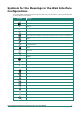
Symbols for the Meanings in the Web Interface Configurations The Web Interface Configuration includes various symbols. For your convenience, refer to the following table for the meanings of the symbols. Symbols Meanings Add Read detailed information Clear all Column selection Refresh Enable/Disable Auto Save When Auto Save is disabled, users need to click this icon to save the configurations.
Symbols Meanings Hide text that is typed into a text box (usually used when typing a password) Show text typed into a text box (usually used when providing password) *The Export function helps users save the current configurations or information for the specific functions. It is located on the upper part of the configuration area. There are two formats available: CVS, or PDF. Select the format and save in your local computer.
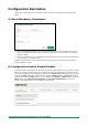
Configuration Reminders In this section, several examples will be used to remind users when configuring the settings for Moxa’s switch. A: About Mandatory Parameters 1. The items with asterisks mean they are mandatory parameters that must be provided. In the figure above, the parameters for VLAN, Version, and Query Interval all need to be provided, or it will not be created or applied. 2. If the item is marked with red it means this item has been skipped.
2. Getting Started In this chapter, we explain how to log in a Moxa’s switch for the first time. There are three ways to access the Moxa switch’s configuration settings: RS-232 console, telnet (disabled by default) or web-based interface. Log in by Web Interface You can directly connect Moxa’s switch to your computer with a standard network cable or install your computer at the same intranet as your switch. Then you need to configure your computer’s network setting.
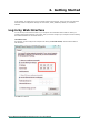
Connecting to the Switch Open a browser, such as Google Chrome, Internet Explorer 11, or Firefox, and connect to the following IP address: https://192.168.127.253 NOTE For network security consideration, all HTTP connections will be automatically redirected to HTTPS connections. The web browser will display a warning message if the device uses a certificate which isn't signed by the certification authority. You may add an exception rule for the certificate in the web browser to continue.
Another system message will appear, reminding you to change the default password. We recommend you change your password, or a message will appear whenever you log in. You can change the password in the Account Management section. Click CLOSE to continue. Log in by RS-232 Console The Moxa’s managed switch offers a serial console port, allowing users to connect to the switch and configure the settings. Do the following steps for the serial connection and configuration. 1.
2. Select Open under the Port Manager menu to open a new connection. 3. The Property window should open. On the Communication Parameter tab for Ports, select the COM port that is being used for the console connection. Set the other fields as follows: 115200 for Baud Rate, 8 for Data Bits, None for Parity, and 1 for Stop Bits. 4. On the Terminal tab, select VT100 for Terminal Type, and then click OK to continue. Moxa’s Managed Switch Next Generation OS (v3.
5. The console will prompt you to log in. The default login name is admin, and the default password is moxa. This password will be required to access any of the consoles (web, serial, Telnet). 6. After successfully connecting to the switch by serial console, users can start configuring the switch parameters by using command line instructions. Refer to the Moxa Command Line Interface Manual. NOTE By default, the password assigned to the Moxa switch is moxa.
NOTE The Moxa switch’s default IP address is 192.168.127.253. After making sure that the Moxa switch is connected to the same LAN and logical subnet as your PC, open the Moxa switch’s Telnet console as follows: 1. Click Start > Run from the Windows Start menu and then Telnet to the Moxa switch’s IP address from the Windows Run window. You can also issue the Telnet command from a DOS prompt. 2. Next, use Telnet to connect the Moxa switch’s IP address (192.168.127.253) from the Windows Run window.
3. The Telnet console will prompt you to log in. The default login name is admin, and the password is moxa. This password will be required to access any of the consoles (web, serial, Telnet). 4. After successfully connecting to the switch by Telnet, users can start configuring the switch parameters by using command line instructions. Refer to the Moxa Command Line Interface Manual. NOTE By default, the password assigned to the Moxa switch is moxa.
3. Web Interface Configuration Moxa’s managed switch offers a user-friendly web interface for easy configurations. Users find it simple to configure various settings over the web interface. All configurations for the Moxa’s managed switch can be easily set up and done via this web interface, essentially reducing system maintenance and configuration effort.
Device Summary After successfully connecting to the switch, the Device Summary will automatically appear. You can view the whole web interface on the screen. If you are in the middle of performing configurations, simply click Device Summary on the Function Menu and you can view the detailed information of the switch. See the following sections for detailed descriptions for the specific items.
Panel Status This section illustrates the panel status. For example, the connecting ports will be shown in green, while the disconnected ports will be shown in gray. Click EXPAND to view more detailed information on the panel status and click Collapse to return. Click EXPAND to view more detailed information on the panel status and click COLLAPSE to return. Moxa’s Managed Switch Next Generation OS (v3.
Panel View Click the icon with four arrows ( ) to view the device port status graphically. Click the close icon in the upper right corner to return to the main page. This appearance of the panel view figure depends on which model is being used, so what you see might be different than the panel view shown below. Event Summary (Last 3 Days) This section shows the event summary for the past three days. Moxa’s Managed Switch Next Generation OS (v3.
Click VIEW ALL EVENTS LOGS to go to the Event Log page, where you can view all event logs. For Event Log settings, refer to Event Log under the Diagnosis section. CPU Utilization History This section shows the CPU usage. The data will be shown as a percentage over time. Click the refresh icon on the page to show the latest information. Moxa’s Managed Switch Next Generation OS (v3.
System Click System on the function menu. You can configure the System Management, Account Management, Network, and Time configurations. System Management Click System Management, four functions can be configured under this section: Information Setting, Firmware Upgrade, Configure Backup and Restore, and Event Log Backup. Moxa’s Managed Switch Next Generation OS (v3.
Information Setting Define Information Setting items to make it easier to identify different switches that are connected to your network. Device Name Setting 1 to 64 characters Description This option is useful for differentiating between the roles or applications of different units. Note that the device name cannot be empty. Factory Default moxa NOTE The Device Name field follows the PROFINET I/O naming rule. The name can only include the following characters, a-z/0-9/-. Location Setting Max.
Firmware Upgrade There are three ways to update your Moxa switch’s firmware: from a local *.rom file, by remote SFTP server, and remote TFTP server. Local Select Local tab. Select File Before performing firmware upgrade, download the updated firmware (*.rom) file first from Moxa’s website (www.moxa.com). Setting Description Click the icon on the right and select the firmware file from Select the firmware file the location where the updated firmware is located. Browse for the (*.
Account Setting Input the account of the SFTP server Description The account must be authorized in order for the SFTP Server to have a secure connection. Factory Default None Password Setting Description Factory Default Input the password for The account has to be specified in order to authorize the SFTP None the SFTP server Server for secure connection. File Name Setting Input the file name of the firmware Description Factory Default Input the file name of the new firmware.
USB You can upgrade the firmware via Moxa's USB-based ABC-02 configuration tool. Connect the ABC-02 to the switch and select USB from the drop-down list under Method. Select File Before performing the firmware upgrade, download the latest firmware (*.rom) file first from Moxa’s website (www.moxa.com). Setting Description Select the firmware file from the location where the updated Select the firmware file firmware is located. Browse for the (*.
Setting Description Select the firmware file from the location where the updated Select the firmware file firmware is located. Browse for the (*.rom) This option allows users to select the updated firmware file file and perform the firmware upgrade. Factory Default None None When finished, click UPGRADE to perform the firmware upgrade.
SFTP Server Click SFTP tab first. Server IP Address Setting Description Input the IP address of Input the IP address of the SFTP server where the new the SFTP server firmware file (*.rom) is located. Factory Default None Account Setting Input the account of the SFTP server Description Factory Default An account must be provided to authorize the SFTP server for None secure connection.
TFTP Server Click TFTP tab first. Server IP Address Setting Description Input the IP address of Users can input the IP address of the TFTP server. the TFTP server Factory Default None File Name Setting Description Factory Default Input the backup/restore file Users can input the file name to back up or restore the system name (supports up to None configuration file. 54 characters, including the .ini file extension). When finished, click BACKUP or RESTORE to perform the firmware upgrade.
microSD Select microSD from the drop-down list under Method. NOTE If you have difficulty using the ABC-03-microSD-T configuration tool, check if the microSD has been enabled in the Hardware Interface section. File Encryption To encrypt the configuration file, click the File Encryption tab first. Enable Configuration File Encryption Setting Enabled Disabled Description Enable the configuration file to be encrypted. Disable the feature that allows the configuration file to be encrypted.
File Signature Click File Signature tab to see additional configuration options. Enabling the file signature can ensure file integrity and authenticity. Enable Signed Configuration Setting Enabled Disabled Description Enable configuration file signature. Disable configuration file signature Factory Default Disabled Click APPLY to save your changes. Click + icon to add customer key. Label Setting 0 to 16 characters Description Provide the name for the certificate and the key.
Key Setting Click the import file icon to select the file from your computer Description Factory Default Import the key file. None When finished, click CREATE to save your changes. Event Log Backup There are three ways to back up Moxa switch’s log files: from a local drive, by remote SFTP server, or by remote TFTP. Local Click Local tab. Click BACKUP to back up the log file to a local drive. SFTP Server Click SFTP tab.
Account Setting Input the account of the SFTP server Description Factory Default An account must be specified to authorize the SFTP server for None secure connection. Password Setting Description Factory Default Input the password for The password has to be entered in order to authorize the SFTP None the SFTP server Server for secure connection. File Name Setting Input the file name for event log backup Description Factory Default Users can input the file name of the event log.
Account Management The Account Management feature allows users to manage the accounts of the switch. You can enable different accounts with different roles to facilitate convenient management and safe access. User Account This section describes how to manage the existing accounts of the switch. Here, you can add, edit, and delete user accounts for the switch. By default, there is only one account: admin. In order to enhance security, we suggest you create a new account with the user authority.
Editing Existing Accounts Select the account you want to edit and click the edit icon. Configure the following settings. Enabled Setting Enabled Disabled Description This enables the user account. This disables the user account. Factory Default Description This account has read/write access for all configuration parameters. This account has read/write access for some specific configuration parameters. This account can only view some specific configuration parameters.
To change the password for the user, click CHANGE PASSWORD. New Password Setting 4 to 63 characters Description Enter the password to use for this account. Factory Default None Description Reenter the password to confirm it. Factory Default None Confirm Password Setting 4 to 63 characters When finished, click APPLY to save your changes. NOTE Refer to Appendix A for detailed descriptions for read/write access privileges for the admin, supervisor, and user authority levels.
Configure the following settings. Enabled Setting Enabled Disabled Description This enables the account. This disables the account. Factory Default Enabled Username Setting Description Input a username, 4 to Input a new username for this account. 32 characters Factory Default None Authority Setting admin supervisor user Description This account has read/write access of all configuration parameters. This account has read/write access for some specific configuration parameters.
Delete an Existing Account To delete the existing account, simply select the account you want to delete, and then click the delete icon on the configuration page. Click DELETE to delete the account. Moxa’s Managed Switch Next Generation OS (v3.
Password Policy In order to prevent hackers from cracking weak passwords, a password policy can be set. The password policy can force users to create passwords with a minimum length and complexity, and can also set a maximum lifetime for the password to ensure it is changed periodically. Minimum Length Setting Input from 4 to 63 Description This sets the minimum length of the password.
Online Accounts The Online Accounts function allows users to view who has connected to the device. You may immediately remove the user who is currently online. Select the remove icon and select REMOVE to disconnect the user. Network This section describes how to configure the switch’s network settings, including IP Configuration and the DHCP Server. Moxa’s Managed Switch Next Generation OS (v3.
IP Configuration Users can configure the IP settings of the switch. Get IP From Setting Manual DHCP Description Factory Default The IP address of the switch must be set manually. The IP address of the switch will be assigned automatically by Manual the network’s DHCP server. IP Address Setting Description Input the IP address for Specify the IP address to use for the switch. the switch Factory Default 192.168.127.
DNS Server 2 Setting Description Specify the IP address of the 2nd DNS server used by your Input the IP address of network. The switch will use the secondary DNS server if the the 2nd DNS server first DNS server fails to connect.
DHCP Server This section describes how to configure the DHCP server settings for Moxa’s switch. First, click the General tab. Then select DHCP/MAC-based IP Assignment and click APPLY. NOTE The DHCP server will use UDP port 67 to send messages to the DHCP client. DHCP Select the DHCP tab and then click the + icon on the configuration page to create a new DHCP server pool. Moxa’s Managed Switch Next Generation OS (v3.
Configure the following parameters. NOTE Users can only create one IP pool. It can be connected to different network subnets with the Management IP of the switch. Enable Setting Enabled Disable Description Enables the DHCP server pool. Disables the DHCP server pool. Factory Default Description Factory Default Specify the first IP address for the pool. None Description Factory Default Specify the subnet mask for the pool.
Default Gateway Setting Description Input the IP address of Specify the default gateway for clients to use. the default gateway Factory Default None Lease Time (sec.) Setting Description Input the lease time for the DHCP, from 10 to Specify the lease time for DHCP IP assignments. 604,800 seconds (up to 7 days) Factory Default 86400 DNS Server 1 Setting Description Factory Default Input the IP address of Specify the IP address of the 1st DNS server for clients to use.
Configure the following parameters. Enable Setting Enabled Disabled Description Enables the MAC-based IP assignment entry. Disables the MAC-based IP assignment entry. Factory Default Description Factory Default Specify a hostname to use for the DHCP client. None Description Factory Default Specify the IP address to assign to the client. None Description Factory Default Specify the subnet mask to use for the client.
MAC Address Setting Description Specify the MAC address of the device you want to assign an Input the assigned MAC IP address to. Make sure the MAC address is entered in the address correct format. Here is an example: 28-d2-44-D3-e3-f2 or 28:d2:44:D3:e3:f2. Factory Default None Default Gateway Setting Description Input the IP address of Specify the default gateway for the client to use. the default gateway Factory Default None Lease Time (sec.
Next, click the Port-based IP Assignment tab, and then click the + icon on the configuration page. Configure the following parameters. Enable Setting Enabled Disabled Description Enables the port-based IP assignment entry. Disables the port-based IP assignment entry. Factory Default Description Select which switch port the DHCP server will assign an IP address for. Factory Default Description Factory Default Specify the IP address to assign to the client.
Subnet Mask Setting Select from the dropdown list Description Factory Default Specify the subnet mask to use for the client. None Default Gateway Setting Description Input the IP address of Specify the default gateway for the client to use. the default gateway Factory Default None Lease Time (sec.) Setting Description Factory Default Input the lease time for the DHCP, from 10 to Define how long before the IP address needs to be reassigned.
Time This section describes how to configure the Time Zone and System Time settings for the switch. The switch has a time calibration function based on information from an NTP server or a user-specified time and date, allowing functions such as automatic warning emails to include a time and date stamp. NOTE The user must update the Current Time and Current Date after the switch has been powered off for an extended period of time (e.g., three days).
Time Zone Setting Select from the dropdown list Description Specify the time zone to use for the switch. Factory Default GMT (Greenwich Mean Time) Daylight Saving Time The Daylight Saving Time settings are used to automatically adjust the time according to regional standards. Configure the following settings. Daylight Saving Time Setting Enabled Disabled Description Enables Daylight Saving Time. Disables Daylight Saving Time.
System Time This section describes how to configure the Time, NTP Server, and NTP Authentication settings. Time The section describes how to configure the system time. Click the Time tab. Current Time Setting None Description This automatically shows the current time according to your default settings. Factory Default Description Specify whether to set the time manually (Local), from an SNTP server, or from an NTP server.
Time Setting Input the current time Description Factory Default Specify the current time. You can manually input the time, or you can click Sync From Browser to set the time based on the None time used by your web browser. Clock Source is from SNTP Time Server 1 Setting Input the address of the 1st SNTP time server Description Specify the IP or domain address of the 1st SNTP server to use (e.g., 192.168.1.1, time.stdtime.gov.tw, or time.nist.gov). Factory Default Time.nist.
Enable Setting Enabled Disabled Description Enable the NTP server. Disable the NTP server. Factory Default Description Enable NTP authentication. Disable NTP authentication. Factory Default Disabled Client Authentication Setting Enabled Disabled Disabled When finished, click APPLY to save your changes. NOTE The NTP server will use TCP port 123 to send messages to the NTP client. NTP Authentication This section describes how to configure NTP Authentication.
Type Setting Input the authentication type Description Factory Default Input the authentication type. MD5 Key String Setting Description Input the key string for authentication, from 0 Input the password to use for the authentication key. to 32 characters. Factory Default None When finished, click CREATE. Port This section describes how to configure the Port Interface, Link Aggregation, and PoE functions for the switch.
Port Setting Under Port Setting, select the Setting tab and then click the edit icon on the port you want to configure. Configure the following parameters. Admin Status Setting Enable Disabled Description Allows data transmission through this port. Disables data transmission through this port. Moxa’s Managed Switch Next Generation OS (v3.
Media Type Setting Media type Description Displays the media type for each module’s port. Factory Default 1000TX,RJ45,PTP Description Specify an alias for the port to help differentiate between different ports (e.g., PLC1). Factory Default Description Allows the port to use the IEEE 802.3u protocol to negotiate with connected devices. The port and connected devices will determine the best speed for that connection. Factory Default Description Setting Max.
Port Status To view the status of the ports, click the Status tab. Linkup Delay Linkup Delay Overview Linkup delay is used to prevent a port alternating between link up and link down. It is also sometimes called link flap prevention. This feature is useful when the link connection is unstable. An unstable connection might be caused by a faulty cable, faulty fiber transceiver, duplex mismatch, etc.
To configure linkup delay for a port, click the edit icon on the port you want to configure. Some parameters need to be configured. Linkup Delay Setting Enable Disable Description Enables linkup delay for the port. Disables linkup delay for the port. Factory Default Description Specify the linkup delay time from 1 to 1000 seconds. Factory Default 2 Setting Description Select the port(s) from Allows you to copy the configurations to other port(s).
Static Trunk For some networking applications, a situation can arise where traffic from multiple ports is required to be filtered through one port. For example, if there are 30 UHD IP surveillance cameras deployed and connected in a ring, the traffic can reach up to 1 Gbps, causing a surge in traffic that can increase network loading by up to 50%. Hence, the uplink port needs to use the static trunk function to provide more bandwidth and redundancy protection.
Config Member Port Setting Select from the ports Description Select the ports you want to create for link aggregation grouping. Factory Default None When finished, click CREATE to continue. You can view the current Link Aggregation or Port Channel (Trunk) status on the configuration page. You can also edit or delete by clicking the edit or delete icon on the page. Editing Port Setting for Link Aggregation To edit each port’s setting for Link Aggregation, click the edit icon on the port name.
When finished, click APPLY to save your changes. Deleting the Port for Link Aggregation To delete the port for Link Aggregation, check the port and then click the delete icon. Click DELETE to finish. Note that some features, such as RSTP and VLAN will be set to default values once you delete the Link Aggregation setting.
PoE Port Settings Click PoE on the menu, and then select the General tab on the configuration page. NOTE Please do not switch Power Management mode, i.e. Allocated Power and Consumed Power, when the device is in operation. Configure the following settings. NOTE Please enable Auto Power Cutting to optimize power usage. Power Output Setting Enable Disable Description Enable PoE for all ports on the switch. Disable PoE for all ports on the switch.
Actual Power Budget (watts) Setting Display the current power budget information Description Show the current power budget information. The lower value between “Actual Power Budget” and “System Power Budget” will become the “Power Budget Limit”. Factory Default 240 When finished, click APPLY to save your changes. Editing PoE Settings for Each Port In this section, you can also enable the PoE function for specific ports even when the system PoE is disabled under the General tab.
Setting Force Description Factory Default Provides power output to non-802.3 af/at/bt PDs when the detected PD has higher/lower resistance or higher capacitance and the acceptable PD resistance range exceeds 2.4 kΩ. The system will prompt you to select Force Mode to allocate 0 to 90 watts of power. Legacy PD Detection The PoE Ethernet Switch includes a Legacy PD Detection function. When the capacitance of the PD is higher than 2.
Moxa’s Managed Switch Next Generation OS (v3.
Configure the following parameters. Enable Setting Enable Disable Description Enable PD failure check for this port. Disable PD failure check for this port. Factory Default Description Specify the PD’s IP address. Factory Default 0.0.0.0 Disabled Device IP Setting Input the device’s IP Check Frequency (sec.) Setting 5 to 300 Description Specify how often the PD failure check will run. Factory Default 10 Description The maximum number of IP checking cycles.
PoE Scheduling Note that this function is only available in Advanced Mode. Powered devices might not need to be running 24 hours a day, 7 days a week. The PoE Ethernet switch includes a PoE scheduling mechanism that allows users to economize the system’s power burden by setting a flexible working schedule for each PoE port. Switch to Advanced Mode, click the Scheduling tab, and then click the + icon to create the scheduling settings. Edit the following parameters.
Rule Name Setting Input the rule name Description Input the name for the scheduling rule. Factory Default None Description Enable PoE Scheduling for this port. Disable PoE Scheduling for this port. Factory Default Description Factory Default Input the start date for the rule. None Enable Setting Enable Disable Disabled Start Date Setting Input start date in the mm/dd/yyyy format Start Time Setting Description Select the start time in Select the start time for the rule.
PoE Status You can view the current PoE setting status by clicking the Status tab. You can view the PoE status for each port. Refer to the following descriptions. Name Port PoE Supported Power Output Classification Current (mA) Voltage (V) Consumption (W) Device Type Configuration Suggestion PD Failure Check Description PoE port on the device. Check if this port supports PoE. Power output status (on/off) for the port. Check the Classification table below for details.
Device Type Item Not Present Legacy PoE Device 802.3bt DS 802.3bt SS NIC Unknown N/A Description No connection to the port. A legacy PD is connected to the port, and the PD has detected that the voltage is too low or high, or the PD’s detected capacitance is too high. An IEEE 802.3bt Dual Signature PD is connected to the port. An IEEE 802.3bt Single Signature PD is connected to the port. A NIC is connected to the port. An unknown PD is connected to the port. The PoE function is disabled.
IEEE 802.1Q Overview The IEEE 802.1Q is a network communication protocol that falls under the IEEE 802.1 standard regulation, allowing various segments to use a physical network at the same time to block broadcast packets by different segmentations. It specifies the VLAN tagging for Ethernet frames on switches that can control the path process.
VLANs and the Moxa switch Your Moxa switch includes support for VLANs using IEEE Std 802.1Q-2005. This standard allows traffic from multiple VLANs to be carried across one physical link. The IEEE Std 802.1Q-2005 standard allows each port on your Moxa switch to be placed as follows: • On a single VLAN defined in the switch • On several VLANs simultaneously using 802.1Q tagging The standard requires that you define the 802.
The following section illustrates how to use these ports to set up different applications. In this application: • Port 1 connects a single untagged device and assigns it to VLAN 5; it should be configured as an Access Port with PVID 5. • Port 2 connects a LAN with two untagged devices belonging to VLAN 2. One tagged device with VID 3 and one tagged device with VID 4. It should be configured as a Hybrid Port with PVID 2 for untagged device and Fixed VLAN (Tagged) with 3 and 4 for tagged device.
To edit the GVRP function, click the Global tab. Configure the following setting. GVRP Setting Disabled Enabled Description Disables GVRP. Enables GVRP. Factory Default Disabled Click APPLY to finish. VLAN Management Port Quick Settings In the lower part of the configuration page, you can quickly configure the VLAN settings. Configure the following settings. Management VLAN Setting Description Select the Management VLAN from the dropShow the list of selectable VLANs.
Detailed VLAN Settings On the IEEE 802.1Q page, first click the Setting tab, and then click the edit icon. Configure the following parameters. VID Setting Input a VLAN ID, (10 VLANs max.) Description Factory Default Input a VLAN ID. None Description Factory Default Specify a name for the VLAN. None Name Setting Input a name for the VLAN, (32 characters max.) Member Port Setting Description Select the port from the Specify the ports that are the member ports for the VLAN. drop-down list.
Editing the Existing VLAN Settings To edit the exiting VLAN settings, click the edit icon of the VLAN you want to edit. Configure the following settings. VID Setting Show the VLAN ID Description Display the VLAN ID. Factory Default None Description Factory Default Display the VLAN name. None Name Setting Show the name of the VLAN Member Port Setting Description Select the port from the Specify the ports that are member ports for the VLAN.
Editing the Port Settings To edit the port settings, in the VLAN tab select the edit icon on the port you want to configure on the lower part of the page. Configure the following settings. Mode Setting Access Trunk Hybrid Description When this port is connected to a single device, without tags. When this port is connected to another 802.1Q VLAN aware switch. When this port is connected to another Access 802.1Q VLAN aware switch or another LAN that combines tagged and/or untagged devices.
Tagged VLAN Setting 1 to 4094 Description This field will be active only when selecting the Trunk or Hybrid port type. Set the other VLAN ID for tagged devices that connect to the port. Factory Default None Untagged VLAN Setting VID range from 1 to 4094 Description This field is only active when the Hybrid port type is selected. Set the other VLAN ID for tagged devices that connect to the port and tags that need to be removed in egress packets.
Join Time (sec.) Setting 10 to 499999980 Description Input the join time from 10 to 499999980 seconds. Factory Default 200 Description Input the leave time from 30 to 499999980 seconds. Factory Default 600 Description Input the leave all time. Factory Default 10000 Leave Time (sec.) Setting 30 to 499999980 Leave All time (sec.) Setting 30 to 499999990 Copy Config to Ports Setting Description Select the port(s) from Copy the configurations to other port(s).
Configure the following settings. VID Setting Input a VLAN ID Description Input a VLAN ID. Factory Default None Description Factory Default Input the MAC address of the port. None MAC Address Setting MAC address of the port Port Setting Description Select the port from the Specify the port you want to create a VLAN for. drop-down list Factory Default None When finished, click CREATE. MAC Address Table Select MAC Address Table, and configure the following settings.
You can view the current MAC Address Table on the bottom part of the configuration page. Item Name Index VLAN MAC Address Type Port Description The number of the MAC address. The VLAN number The MAC address on this device. Learnt Unicast, Learnt Multicast, Static Unicast, Static: Multicast The forwarding port of this MAC address. QoS This section describes how QoS works and how to configure the settings.
Moxa switch traffic prioritization is based on two standards: • IEEE 802.1p—a layer 2 QoS marking scheme • Differentiated Services (DiffServ)—a layer 3 QoS marking scheme. IEEE 802.1p Class of Service The IEEE Std 802.1D 2005 Edition marking scheme, which is an enhancement to IEEE Std 802.1D, enables Quality of Service on the LAN. Traffic service levels are defined in the IEEE 802.1Q 4-byte tag, which is used to carry VLAN identification as well as IEEE 802.1p priority information. The IEEE 802.
Traffic Prioritization Moxa switches classify traffic based on layer 2 of the OSI 7 layer model, and the switch prioritizes outbound traffic according to the priority information defined in the received packet. Incoming traffic is classified based upon the IEEE 802.1p service level field and is assigned to the appropriate egress priority queue. The traffic flow through the switch is as follows: • A packet received by the Moxa switch may or may not have an 802.1p tag associated with it.
Configure the priority setting from the drop-down list for this port. DSCP Value and Priority Setting 0 to 7 8 to 15 16 to 23 24 to 31 32 to 39 40 to 47 48 to 55 56 to 63 Description Different DSCP values map to one of eight different priorities from 0 to 7. Factory Default 0 1 2 3 4 5 6 7 When finished, click APPLY to save your changes. CoS to Queue Mapping In the Classification menu, click the CoS Mapping tab, and then click the edit icon. Configure the Queue priority setting for the port.
Queue Priority Setting 0 1 2 3 4 5 6 7 Description Different 802.1p values map to one of the eight different queues from 1 (lowest priority) to 8 (highest). Factory Default 1 2 3 4 5 6 7 8 When finished, click APPLY to save your changes. Port Settings In the Classification menu, click the Port Setting tab, and then click the edit icon. Configure the following settings. Trust Type Setting CoS DSCP Description Enables the port with CoS-based traffic classification.
Untag Default Priority Setting 0 to 7 Description Factory Default 802.1p tag (CoS) can be range from 0 (lowest) to 7 (highest). 3 Copy Config to Ports Setting Select from the dropdown list Description Factory Default Copy the settings to other ports you select. None When finished, click APPLY to save your changes. Ingress Rate Limit Exceed Rate Limit Threshold Port Shutdown In general, any user shall not consume unlimited bandwidth and influence others' access.
Editing the Port for Port Shutdown Edit the specific port that you want to edit the port shutdown configurations for. Configure the following settings. Enable Setting Enable Disable Description Enable port shutdown for this port. Disable port shutdown for this port.
Strict Priority The Strict Priority type allows users to determine to transmit packets in the highest priority queue first, while packets with lower priority will be transmitted later. This guarantees that traffic with the highest level of priority for data transmission will go first. Weighted Round Robin The Weighted Round Robin type allows users to give priority to specific packets in the higher weighted queue to ensure those packets will be sent first.
Multicast Multicast filtering improves the performance of networks that carry multicast traffic. This section will explain the Layer 2 multicast settings, such as IGMP Snooping, GMRP, and Static Multicast. IGMP Snooping IGMP Snooping Overview IGMP stands for Internet Group Management Protocol, which is a network communication protocol that hosts nearby routers on networks to construct multicast group memberships.
With IGMP Snooping Differences Between IGMP Snooping V1, V2, and V3 IGMP protocols regulate the communication mechanism between querier and listener. IGMP Snooping has three different versions. Refer to the following table for the detailed differences. IGMP Version V1 V2 V3 Main Features The IGMPv1 querier will periodically send out a "query". Listeners can solicit a "report" of their interested group.
Configuring VLAN Setting Click the VLAN Setting tab, and then click the edit icon to configure the VLAN settings. Enable Setting Enabled Disabled Description Enable IGMP Snooping on a switch. Disable IGMP Snooping on a switch. Factory Default Disabled Version Setting 1, 2, 3 Description Factory Default Specify the IGMP version of the packets that the switch listens 2 to and send queries for.
Static Router Port Setting Description The router port is the port that connects to the upper level router (or IGMP querier), or to the upper level router of Check the port from the downstream multicast streams. All of the received IGMP drop-down list signaling packets or multicast streams will be forwarded to those static router ports. Factory Default None Config Role Setting Querier Non-Querier Description The switch will act as the Querier role. The switch will not act as the Querier role.
Refer to the following table for a description of each item. Item VLAN Group Address Source Address Port Description The VLAN ID. The associated multicast group address of the streaming data. The source address of the streaming data. The forwarded port. GMRP GMRP stands for GARP Multicast Registration Protocol, which is a Generic Attribute Registration Protocol (GARP) application that can be used to prevent multicast from data flooding. Both GMRP and GARP are defined by the IEEE 802.
Configure the following settings. Enable Setting Enabled Disabled Description Enable GMRP for this port. Disable GMRP for this port. Factory Default Description Enable Group Restrict on the port. This specific port will not process any GMRP control packets. Disable Group Restrict on the port. The specific port will receive and process incoming GMRP control packets.
Configure the following settings. VID (VLAN ID) Setting Input the VID Description Specify the multicast group's associated VLAN ID. Factory Default None MAC Address Setting Description Input the MAC address Specify the multicast MAC address. Factory Default None Egress Port Setting Description Factory Default Input the port from the Set the port(s) as an egress port(s) so that multicast streams None drop-down list can be forwarded to this port.
Layer 2 Redundancy First select Network Redundancy on the menu and then click Layer 2 Redundancy. Spanning Tree Spanning Tree Overview Spanning Tree Protocol (STP) was designed to help construct a loop-free logical typology on an Ethernet network, and provide an automatic means of avoiding any network loops. This is particularly important for networks that have a complicated architecture, since unintended loops in the network can cause broadcast storms. Moxa switches’ STP feature is disabled by default.
If STP is enabled, it will detect duplicate paths or block one of the paths from forwarding traffic. In the following example, STP determined that traffic from segment 2 to segment 1 flows through switches C and A since this path is in a forwarding state and is processing BPDUs. However, switch B on segment 1 is in a blocking state.
STP/RSTP Settings and Status This section describes how to configure Spanning Tree settings. General Click Spanning Tree on the menu and then select the General tab. Configure the following settings. STP Mode Setting Disabled STP/RSTP MSTP Description Disable Spanning Tree. Specify STP/RSTP as the STP mode. Specify MSTP as the STP mode. Factory Default Disabled Click APPLY to save your changes. When STP/RSTP has been selected, configure the following settings.
Hello Time (sec.) Setting 1 or 2 Description Factory Default The root of the Spanning Tree topology periodically sends out a “hello” message to other devices on the network to check if 2 the topology is healthy. The “hello time” is the amount of time the root waits between sending hello messages. Max Age (sec.) Setting 6 to 40 Description Factory Default If this device is not the root, and it has not received a hello message from the root in the amount of time equal to “Max.
Max Age (sec.) Setting 6 to 40 Description Factory Default If this device is not the root, and it has not received a hello message from the root in the amount of time equal to “Max. Age,” then this device will reconfigure itself as a root. Once 20 two or more devices on the network are recognized as a root, the devices will renegotiate a new Spanning Tree topology. Error Recovery Time (sec.
Configure the following settings. Enable Setting Enabled Disabled Description Enable Spanning Tree. Disable Spanning Tree. Factory Default Description Automatically detect to be the edge port. Set as an edge port. Do not set as an edge port. Factory Default Disabled Edge Setting Auto Yes No Auto Priority Setting 0 to 255 (multiples of 16) Description Factory Default Increase the priority of a port by selecting a lower number.
Click APPLY to finish. BPDU Overview BDPUs (Bridge Protocol Data Units) are the network communication frames used in the STP (Spanning Tree Protocol). When two switches exchange messages, BDPUs are used to calculate the STP topology, and determine the network communication route. A BDPU filter is often used to screen sending or receiving BPDUs on a specific port of the switch. BPDU Guard BDPU Guard is a protection mechanism that prevents a port from receiving BPDUs.
Configure the following settings. BDPU Guard Setting Enabled Disabled Description Enable BDPU Guard. Disable BDPU Guard. Factory Default Disabled NOTE To establish a redundant port e.g. it is highly recommended that you do not enable BPDU filter. Root Guard Setting Enabled Disabled Description Enable Root Guard. Disable Root Guard. Factory Default Description Enable Loop Guard. Disable Loop Guard. Factory Default Description Enable BDPU Filter. Disable BDPU Filter.
Viewing Current Spanning Tree Status Click the Status tab to view the current Spanning Tree status. In addition, the status for each port will also be shown below. Refer to the following table for detailed description of each item. Item Port Edge Port Rule Port State Root Path Cost Path Cost Link Type BPDU Inconsistency Root Inconsistency Loop Inconsistency Description The port number on this device. Show if this port is connected to an edge device.
Turbo Ring v2 Turbo Ring v2 Overview Moxa Turbo Ring is a proprietary self-healing technology that enables fast fault recovery of under 20 ms for Fast Ethernet, and 50 ms for Gigabit Ethernet. Turbo Ring supports two topology expansions—ring coupling and dual-ring—to reduce redundant network cabling and network planning costs and to ensure high reliability of your industrial network applications.
Dual-Ring Dual-Ring adds reliability by using a single Moxa switch to connect two separate rings for applications that present cabling difficulties. It provides another ring coupling configuration where two adjacent rings can share one switch. This typology is an ideal solution for applications that have inherent cabling difficulties.
For Turbo Ring V2, Ring Coupling is enabled by configuring the Coupling Port (Primary) on Switch B, and the Coupling Port (Backup) on Switch A only. The Coupling Port (Backup) on Switch A is used for the backup path, and connects directly to an extra network port on Switch C. The Coupling Port (Primary) on Switch B monitors the status of the main path, and connects directly to an extra network port on Switch D.
Ring Settings In Ring Setting, click the edit icon. Configure the following settings. When finished, click Apply to save your changes. Enable Setting Enabled Disabled Description Enable Ring Setting. Disable Ring Setting. Factory Default Description Enable this Ring as the Master. Disable this Ring as the Master. Factory Default Disabled Master Setting Enabled Disabled Disabled Ring Port 1 Setting Description Select the port from the Specify this port as the 1st redundant port.
Ring Coupling Settings and Status In the Ring Coupling Setting, click the edit icon. Configure the following settings. Enable Setting Enabled Disabled Description Enable Ring Coupling. Disable Ring Coupling. Factory Default Description Select Coupling Mode to assign the coupling port as the backup path. Select Coupling Mode to assign the coupling port as the primary path.
Ring Settings and Ring Coupling Setting Status Click Status in the Turbo Ring V2 menu to view the current Ring settings and the Ring Coupling Status. Refer to the following table for a detailed description for each item of the Ring status. Item Ring ID Master ID Status Master Ring Port 1 Ring Port 2 Description The ID number of the Ring. The MAC address of the Ring Master. Healthy: The Ring and the ports are working properly. Break: One or more Rings have been broken.
How Turbo Chain Works Moxa’s Turbo Chain outperforms traditional ring topologies by providing great flexibility, unrestricted expansion, and cost-effective configurations when connecting separate redundant rings together—in a simplified manner. With Turbo Chain, you can create any complex redundant network that correspond to your needs, while still ensuring great reliability and availability for your industrial Ethernet network applications.
There are two points to note: 1. Two Chain ports must have the same PVID. 2. Chain ports must join the untagged members of PVID VLAN before being assigned to be a Chain port. Turbo Chain V2 Settings and Status First select Turbo Chain on the menu and then click Setting. Configure the following settings. Enable Setting Enabled Disabled Description Enable Turbo Chain. Disable Turbo Chain. Factory Default Description Enable chain role as the Head. Enable chain role as a Member.
Select Turbo Chain on the menu and click Status to view the current Turbo Chain status. Refer to the following table for a detailed description of each item. Item Turbo Chain Chain Role Head/Member/Tail 1 Port Status Head/Member/Tail 2 Port Status Description Head: The device is the head of this chain. Member: The device is a member of this chain. Tail: The device is the tail of this chain. Healthy: The Chain and the ports are working properly. Break: The chain or the ports are broken.
Path Switching Mode There are two path switch modes that users can configure: Primary path always first: Always selects the path switching mode as the primary path first. When path switching occurs, the primary path will always be the first path for data communication. Maintain current path: Select the path switching mode to maintain the current path. When path switching occurs, maintain the current path to keep the network stable and do not change paths for data communication.
Secondary Port Setting Description Select the port from the Specify the port as the secondary port. list Factory Default 1/1 Path Switching Mode Setting Primary path always first Maintain current path Description Always selects path switching mode as the primary path first. Always selects the path switching mode to maintain the current path. Factory Default Primary path always first When finished, click APPLY to save your changes.
Network Management This section demonstrates how to configure SNMP and SNMP Trap/Inform settings. SNMP Moxa switches support SNMP V1, V2c, and V3. SNMP V1 and SNMP V2c use a community string match for authentication, which means that SNMP servers access all objects with read-only or read/write permissions using the community strings public and private by default. SNMP V3 requires that you select an authentication level of MD5 or SHA. You can also enable data encryption to enhance data security.
Configure the following settings. SNMP Version Setting V1, V2c, V3 V1, V2c V3 only Description Specify V1, V2c, and V3 as the SNMP version. Specify V1 and V2c as the SNMP version. Specify V3 as the SNMP version. Factory Default Description Specifies the community string to authenticate the SNMP agent for read-only access. The SNMP agent will access all objects with read-only permissions using this community string. Factory Default V1, V2c Read Community Setting Max.
Username Setting At least 4 characters, (max. 32 characters) Description Factory Default Input a username. None Description The user has read/write access. The user only has read access. Factory Default Description No authentication will be used. MD5 is the authentication type. SHA is the authentication type.
SNMP Trap/Inform General Settings First select SNMP Trap/Inform on the menu and then click General. Configure the following settings. Retry Setting 1 to 99 Description Input the retry value. Factory Default 3 Description Input the timeout value. Factory Default 10 Timeout Setting 1 to 300 When finished, click APPLY to save your changes. SNMP Trap Host Settings SNMP Trap allows an SNMP agent to notify the NMS of a significant event. The switch supports two SNMP modes: Trap mode and Inform mode.
Configure the following settings. Host IP/Name Setting Input a host IP or name, (max. 32 characters) Description Factory Default Specify the name of the primary trap server used by your network. None Mode Setting Trap V1 Trap V2c Inform V2c Trap V3 Inform V3 Description Set the trap version to Trap V1. Set the trap version to Trap v2c. Set the inform version to Inform V2c. Set the trap version to Trap V3. Set the inform version to Inform V3.
Configure the following settings Username Setting At least 4 characters, (max. 30 characters) Description Factory Default Input a username. None Description No authentication type will be used. MD5 is the authentication type. SHA is the authentication type. Factory Default Authentication type Setting None MD5 SHA None Authentication Password Setting 8 to 64 characters Description Input the authentication password. Factory Default None Description Disable the encryption method.
Device Security This section includes information about the Management Interface, Login Policy, Trusted Access, and SSH & SSL configurations. Management Interface Click Management Interface to configure the settings for User Interface and Hardware Interface. User Interface Moxa’s Managed Switch Next Generation OS (v3.
Configure the following settings. HTTP Setting Enabled Disabled Description Enable the HTTP connection. Disable the HTTP connection. Factory Default Enabled NOTE An HTTP session will be redirected to HTTPs if both HTTP and HTTPs are enabled. HTTP – TCP Port Setting 0 to 47808 Description Specify the HTTP connection port number. Factory Default 80 Description Enable the HTTPS connection. Disable the HTTPS connection. Factory Default Description Specify the HTTP connection port number.
NOTE Moxa Service is only for Moxa network management software suite. Moxa Service (Encrypted) – TCP Port Setting 443 (read only) Description Enable a Moxa Service TCP port. Factory Default 443 Moxa Service (Encrypted) – UDP Port Setting 40404 (read only) Description Enable a Moxa Service UDP port. Factory Default 40404 Maximum number of Login Sessions for HTTP+HTTPS Setting 1 to 10 Description Specify the maximum amount of HTTP and HTTPS login sessions that can happen at the same time.
Login Policy Click Login Policy on the menu. Configure the following settings. Login Message Setting 0 to 500 characters Description Input the message that will be displayed to users when they log in. Factory Default None Login Authentication Failure Message Setting 0 to 500 characters Description Factory Default Input the message that will be displayed when users fail to log None in.
Auto Logout Setting (min.) Setting 0 to 1440 Description Specify how long a user has to be inactive before getting logged out. Factory Default 5 When finished, click APPLY to save your changes. Trusted Access Trusted Access Overview Trusted Access is a mechanism that provides a secure connection to Moxa’s switch. Users can use this method to allow the connection from the assigned IP address to ensure safe data transmission. Trusted Access Settings and Status Click Trusted Access on the menu.
Next, click the + icon. Configure the following settings. IP Address Setting Input IP address Description Specify the IP address that is allowed to connect to Moxa’s switch. Factory Default Description Specify the Netmask that is allowed to connect to Moxa’s switch. Factory Default None Netmask Setting Input Netmask None When finished, click CREATE. You can view the Trusted Access status on the figure below. Moxa’s Managed Switch Next Generation OS (v3.
To delete the trusted access source, select the item and then click the delete icon on the top of the page. Click DELETE to delete the item. SSH & SSL SSH Key Regeneration Click SSH & SSL on the menu and then select the SSH tab. Click REGENERATE to regenerate the key. Moxa’s Managed Switch Next Generation OS (v3.
SSL Certification Regeneration Click SSH & SSL on the menu and select the SSL tab. The Certificate Information is shown on this screen. We recommend using a certificate that is signed by the certification authority to enhance security. Configure the following settings and use the steps below to import the certificate. 1. Export the CSR file from the switch and provide it to the certification authority to generate the certificate. 2.
Network Security This section demonstrates how to configure network security settings, including IEEE802.1X, MAC Authentication Bypass, Port Security, Traffic Storm Control, Access Control List, and Loop Protection. IEEE 802.1X Port-based IEEE 802.1X Overview The IEEE 802.1X standard defines a protocol for client/server-based access control and authentication.
software to run on the client that offers credentials to the authenticator. Network administrators usually use an Ethernet switch or wireless access point as the authenticator, and running software supporting RADIUS and EAP protocols in the authentication server. The authenticator serves as a security guard to a protected network. The supplicant is not allowed access through the authenticator to the protected side of the network unless the supplicant’s identity has been validated and authorized. With 802.
Configure the following settings. Enable Setting Enabled Disabled Description Enable IEEE 802.1X. Disable IEEE 802.1X. Factory Default Description The controlled port has to be held in the Unauthorized state. The controlled port is set to the authorized or unauthorized state in accordance with the outcome of an authentication exchange between the Supplicant and the Authentication Server. The controlled port is required to be held in the authorized state.
Quiet Period (sec.) Setting 0 to 65535 Description Factory Default Specify the duration of time that the switch remains in the quiet state following a failed authentication exchange with the 60 client. Reauthentication Setting Enabled Disabled Description Enable re-authentication. Disable re-authentication. Factory Default Description Input the duration of time between re-authentication attempts. Factory Default Disabled Reauth Period (sec.) Setting 1 to 65535 3600 Server Timeout (sec.
To configure RADIUS settings, click the RADIUS tab. Configure the following settings. Server Address 1 Setting Description To input server address Specify the 1st server address. 1 Factory Default None Auth Port Setting 1 to 65535 Description Specify the authentication port number for the 1st server address. Factory Default None Share Key Setting Description Input the share key for the 1st server, (0 to Specify the share key for the 1st server. 46) Factory Default None Timeout (sec.
Auth Port Setting 1 to 65535 Description Specify the authentication port number for the 1st server address. Factory Default None Share Key Setting Description Input the share key for the 2nd server (0 to Specify the share key for the 2nd server. 46) Factory Default None Timeout Setting 1 to 120 Description Specify the duration of time before the device is timed out. Factory Default None Description Specify the time for data re-transmission. Factory Default None Retransmit (sec.
Username Setting 0 to 20 characters Description Specify the username for the local database. Factory Default None Description Factory Default Specify the password for the local database user. None Description Factory Default Confirm the password for the local database user. None Password Setting At least 4 characters, (max. 64 characters) Confirm Password Setting At least 4 characters, (max. 64 characters) When finished, click APPLY to save your changes.
RADIUS Click the RADIUS tab to perform further configurations. Configure the following settings. Server Address 1 Setting Description To input server address Specify the 1st server address. 1 Factory Default None Auth Port Setting 1 to 65535 Description Specify the authentication port number for the 1st server address. Factory Default None Share Key Setting Description Input the share key for the 1st server, (0 to Specify the share key for the 1st server. 46) Factory Default None Timeout (sec.
Server Address 2 Setting Description To input server address Specify the 2nd server address. 2 Factory Default None Auth Port Setting 1 to 65535 Description Specify the authentication port number for the 1st server address. Factory Default None Share Key Setting Description Input the share key for the 2nd server (0 to Specify the share key for the 2nd server. 46) Factory Default None Timeout Setting 1 to 120 Description Specify the duration of time before the device is timed out.
MAC Address Setting MAC Address Description Factory Default Specify the MAC address used for MAC authentication bypass. None When finished, click CREATE to complete. Port Security MAC Sticky Overview MAC Sticky is a function that allows users to configure the maximum number of MAC addresses (the Limit) that a port can “learn”.
Click the edit icon on the port you want to edit. Configure the following settings. MAC Sticky Setting Enabled Disabled Description Enable Static Port Lock for this port. Disable Static Port Lock for this port. Factory Default Description Specify the maximum numbers of the learned MAC address. Factory Default 1 Description Enable port shutdown when a violation occurs. Drop the packets when a violation occurs.
Next, click the MAC Sticky tab, and then click the + icon to add the MAC Sticky entries. Configure the following settings. Port Setting Description Select the port from the Select the port(s) that will be used with the MAC Sticky drop-down list function. Factory Default None VLAN ID Setting Input the VLAN ID Description Specify the VLAN ID that will be used with MAC Sticky.
You can view the MAC Sticky settings in the figure below. Static Port Lock Overview To provide a port-based security function, Moxa’s switches have implemented Static Port Lock function; the main idea is to allow configured devices, 128 at most, to access the network through a specific port. Packets sent from unknown devices or from configured devices with mismatching ports will be dropped.
Select Static Port Lock and click APPLY. Select the edit icon on the port you want to edit. Configure the following settings. Enable Setting Enabled Disabled Description Enable Static Port Lock. Disable Static Port Lock. Factory Default Disabled When finished, click APPLY to save your changes. Next, click the Static Port Lock tab and then the + icon to perform further settings. Moxa’s Managed Switch Next Generation OS (v3.
Configure the following settings. Port Setting Description Select the port from the Specify the port(s) that will be used with Static Port Lock. drop-down list Factory Default None VLAN ID Setting Input the VLAN ID Description Specify the VLAN ID that will use Static Port Lock. Factory Default None MAC Address Setting Description Factory Default Input the MAC address Specify the MAC Address of the device that will be used as the None that will be used reliable source for network access.
Traffic Storm Control A traffic storm can happen when packets flood the network; this causes excessive traffic and slows down the network performance. To counter this, Traffic Storm Control provides an efficient design to prevent the network from flooding caused by a broadcast, multicast, or unicast traffic storm on a physical network layer. The feature can handle packets from both ingress and egress data.
Multicast Setting Enabled Disabled Description Enable multicast when a traffic storm occurs. Disable multicast when a traffic storm occurs. Factory Default Description Enable DLF when a traffic storm occurs. Disable DLF when a traffic storm occurs. Factory Default Description Define the threshold for a traffic storm.
Configure the following settings. Access List Type Setting IP-based MAC-based Description Specify IP-based as the access list type. Specify MAC-based as the access list type. Factory Default None Index (For IP-based type) Setting Select from IP-1 to IP16 Description Factory Default Select from the drop-down list for index. None Index (For MAC-based type) Setting Select from MAC-1 to MAC-16 Description Factory Default Select from the drop-down list for index.
IP-based Rule Index Settings Click the icon for Rule Index settings. Configure the following settings. Rule Index 1 Setting Enabled Disabled Description Enable Rule Index 1 settings. Disable Rule Index 1 settings. Factory Default Description Permit the rule type. Deny the rule type. Factory Default Enabled Rule Type Setting Permit Deny None Protocol Setting Description Select the port(s) from Select the protocol used for this rule index.
Destination IP Mask Setting Description Select the port(s) from Select the destination IP mask from the list. the drop-down list Factory Default None DSCP Setting 0 to 63 Description Specify the DSCP value. Factory Default Any When finished, click CREATE to complete. Note that the following system packets are not included in the ACL operation.
MAC-based Rule Index Settings Click the icon for Rule Index settings. Configure the following settings. Rule Index 1 Setting Enabled Disabled Description Enable Rule Index 1 settings. Disable Rule Index 1 settings. Factory Default Description Permit the rule type. Deny the rule type. Factory Default Description Select User defined as the Ethernet type.
Source MAC Mask Setting Description Select the port(s) from Select the source MAC mask from the list. the drop-down list Factory Default None Destination MAC Address Setting MAC address Description Provide the MAC address as the destination MAC address. Factory Default Any Destination MAC Mask Setting Description Select the port(s) from Select the destination MAC mask from the list.
Access Control List Status Click Status to view the Access Control List status. Loop Protection Click Loop Protection on the function menu. Settings Click Settings for further configurations. Configure the following settings. Loop Protection Setting Enabled Disabled Description Enable the Loop Protection function. Disable the Loop Protection function. Moxa’s Managed Switch Next Generation OS (v3.
Detect Interval Setting 1 to 30 Description Specify the detect interval value. Factory Default 10 When finished, click APPLY to complete. Status Click Status tab to view the Loop Protection status. Authentication This section describes how to configure system authentication including RADIUS and TACACS+. Moxa switches have three different user login authentications: TACACS+ (Terminal Access Controller AccessControl System Plus), RADIUS (Remote Authentication Dial In User Service), and Local.
This section includes the configurations for Login Authentication, RADIUS, and TACACS+. Login Authentication This section allows users to select the login authentication protocol. Select Login Authentication. Configure the following settings. Authentication Protocol Setting Local RADIUS TACACS+ RADIUS, Local TACACS+, Local Description Select Local as the authentication protocol. Select RADIUS as the authentication protocol. Select TACACS+ as the authentication protocol.
RADIUS Click RADIUS on the menu and configure the following settings. Server Address 1 Setting Input the server address Description Factory Default Specify the 1st server address as the authentication database. 0.0.0.0 UDP Port Setting Input the port number Description Specify the UDP port. Factory Default 1812 Description Input the share key for 1st server authentication verification. Factory Default None Share Key Setting Input the key Moxa’s Managed Switch Next Generation OS (v3.
Authentication Type Setting PAP CHAP MS-CHAPv1 Description PAP is the authentication type. CHAP is the authentication type. MS-CHAPv1 is the authentication type. Factory Default Description When waiting for a response from the server, set the amount of time before timeout. Factory Default CHAP Timeout (sec.) Setting 5 to 180 5 Retry (sec.) Setting 0 to 5 Description Factory Default Define the retry interval when trying to reconnect to a server.
TACACS+ Click TACACS+ on the menu and then configure the following settings. Server Address 1 Setting Input the server address Description Factory Default Specify the 1st server address as the authentication database. 0.0.0.0 TCP Port Setting Input the port number Description Specify the UDP port. Factory Default 49 Description Specify the share key for 1st server authentication verification. Factory Default Share Key Setting Input the key Moxa’s Managed Switch Next Generation OS (v3.
Authentication Type Setting ASCII PAP CHAP Description ASCII is the authentication type. PAP is the authentication type. CHAP is the authentication type. Factory Default Description When waiting for a response from the server, set the amount of time before the device is timed out. Factory Default Description Set the retry interval when trying to reconnect to a server. Factory Default 1 Description Specify the 2nd server address as the authentication database. Factory Default CHAP Timeout (sec.
Diagnostics This section describes the diagnostics functions of Moxa’s switch. Click Diagnostics on the function menu. System Status This section allows users to view the current system status including Utilization, Statistics, and Module Information. Utilization Click Utilization on the function menu to view the current utilization status including CPU utilization, memory history, power consumption, and power history.
Memory Utilization Setting Read-only Description Displays the memory status. Factory Default None Memory Usage History Setting Read-only Description Displays the history of the memory usage. Factory Default None Power Consumption (watt) Setting Read-only Description Displays the power consumption status. Factory Default None Description Displays the history of the power usage. Factory Default None Power Usage History Setting Read-only Statistics Click Statistics on the function menu.
The status of the different ports will be shown in different colors. A maximum of five ports will have their information displayed. There are four icons on the right upper corner of the page. The table below provides a description for each one. Item Name Description Refresh All statistical data will be refreshed. Reset Statistics Graph The packet counter will be cleared and the graphs will be reset. Display Setting All selected setting items will be shown here.
Display Setting Click the Display Setting icon and all settings will be displayed. You can select the display mode from the drop-down list. The Monitoring Port is the port you want to view or monitor. The sniffer port is the port that you can choose to view its receiving or transmission status or both. Display Mode Setting Packet Counter Bandwidth Utilization Description The packet statistics will be displayed. The bandwidth statistics will be displayed.
The data comparison figure will be shown. Click Close to finish. The detailed packet transmission activity for each port can be seen in the table below. Port: port number Tx Total Octets: Number of octets transmitted including bad packets and FCS octets. Framing bits are not included. Moxa’s Managed Switch Next Generation OS (v3.
Tx Total Packets: Number of packets transmitted. Tx Unicast Packets: Number of Unicast packets transmitted. Tx Broadcast Packets: Number of good Broadcast packets transmitted. Multicast packets are not included. Rx Total Octets: Number of octets received, including bad packets and FCS octets. Framing bits are not included. Rx Unicast Packets: Number of Unicast packets received. Rx Multicast Packets: Number of Multicast packets received. Rx Broadcast Packets: Number of good Broadcast packets received.
Event Notification There are two functions within Event Notification: System and Function, and Port. In the Event Notification menu, click the System and Function tab, and then click the edit icon on the specific event you want to configure. For example, select the edit icon for warm start when the switch reboots. Configure the following settings. Enable Setting Enabled Disabled Description Enable Event Notification for this event. Disable Event Notification for this event.
Next, in the Event Notification menu, click the Port tab, and then click the edit icon on the specific port status on Event Name. For example, select the edit icon for event notifications when the port status is on. Configure the following settings. Enable Setting Enabled Disabled Description Enable Event Notification for this event. Disable Event Notification for this event. Factory Default Description Send SNMP Trap for event notifications. Send an email for event notifications.
When finished, click APPLY to save your changes. In addition, use the same method to edit other events such as, port status is off, port shutdown by port security, and port recovery by rate limit, etc. Check the following table for the severity degree of each event.
Moxa’s switches offer three sets of relay outputs, one on the mainboard and two on the power modules, providing the secured protection of the remote switch and secure data communication. In addition, email notifications can also be sent to inform system administrators to perform further checks and maintenance. Relay Output Settings and Status To select Relay Output as the event notifications, click Relay Output on the function menu. Relay Setting Relay Description Trigger Relay for event notifications.
TCP Port Setting 1 to 65535 Description The TCP port number of your email server. Factory Default 25 Description Your email account name. Factory Default None Description Your email account password. Factory Default None Description Enable TLS (Transport Layer Security). Disable TLS (Transport Layer Security). Factory Default Description The sender’s email address. Factory Default admin@localhost User Name Setting Max. of 60 characters Password Setting Max.
Syslog Settings Click the General tab on the function menu and configure the following settings. Logging Enable Setting Enabled Disabled Description Enable logging. Disable logging. Factory Default Description Enable the 1st log server. Disable the 1st log server. Factory Default Description Input the IP address of the Syslog 1st server that is used by your network. Factory Default Description Input the UDP port number. Factory Default 514 Description Enable the 2nd syslog server.
Address 2 Setting IP Address Description Factory Default Input the IP address of Syslog 2nd server that is used by your None network. UDP Port Setting 1 to 65535 Description Input the UDP port number. Factory Default 514 Description Enable the 3rd syslog server. Disable the 3rd syslog server. Factory Default Description Input the IP address of the Syslog 3rd server that is used by your network. Factory Default Description Input the UDP port number.
Configure the following settings. Client Certificate Setting Description Click the import icon and select the file from Import the client certificate file. your computer. Factory Default None Client Key Setting Description Click the import icon and select the file from Import the client key file. your computer. Factory Default None CA Key Setting Description Click the import icon and select the file from Import the CA key file. your computer.
LLDP Overview LLDP is an OSI Layer 2 protocol defined by IEEE 802.11AB. LLDP standardizes the self-identification advertisement method, and allows each networking device, such as a Moxa managed switch, to periodically send its system and configuration information to its neighbors. Because of this, all LLDP devices are kept informed of each other’s status and configurations. With SNMP, this information can be transferred to Moxa’s MXview for auto-topology and network visualization.
Enable Setting Enabled Disabled Description Enable LLDP. Disable LLDP. Factory Default Setting Description Show the LLDP version Show the LLDP version automatically. Factory Default 2005 Disabled LLDP Version Transmit Interval (sec.) Setting 5 to 32768 Description Set the transmit interval of LLDP messages Factory Default 30 Notification Interval (sec.) Setting 5 to 3600 Description Specify the notification interval. Factory Default 5 Description Specify the Tx delay interval.
Configure the following settings. Port Status Setting Tx Only Rx Only Tx and Rx Description Set Tx as the port status. Set Rx as the port status. Set both Tx and Rx as the port status. Factory Default Description Select If-Alias as the subtype. Select Port-Component as the subtype. Select MAC-Address as the subtype. Select If-Name as the subtype. Select Local as the subtype. Factory Default Description Set TLV as Basic. Set TLV as 802.1. Set TLV as 802.3.
When finished, click APPLY to save your changes. To view the LLDP status, click the Status tab on the LLDP page, and the status of all LLDP will be shown on the page. Refer to the following table for the detailed description of each item. Local Information Enable LLDP Version Chassis ID Subtype Show if LLDP has been enabled or disabled. Show the LLDP version. Show the chassis ID subtype. Chassis ID Show the chassis ID. Local Timer Transmit Interval (sec.) Notification Interval (sec.) Tx Delay (sec.
To view the LLDP status for a specific port, click the detailed information icon on the port. All information will be shown on the right side of the page. Port Mirroring Port Mirroring Overview The Port Mirroring function can be used to monitor data being transmitted through a specific port. This is done by setting up another port (the mirror port) to receive the same data being transmitted from, or both to and from, the port under observation.
Port Mirror Settings and Status Click Port Mirror on the menu and then configure the settings. Enable Setting Enabled Disabled Description Enable Port Mirror. Disable Port Mirror. Factory Default Enabled When finished, click APPLY to save your changes. To configure the specific port, click the edit icon next to the port. Configure the following settings. Moxa’s Managed Switch Next Generation OS (v3.
Enable Setting Enabled Disabled Description Enable Port Mirror for this session. Disable Port Mirror for this session. Factory Default Setting Description Select the port from the Select this option to monitor only those data packets being list sent out through the switch’s port. Factory Default Disabled Tx Source Port None Rx Source Port Setting Description Select the port from the Select this option to monitor only those data packets coming list into the switch’s port.
ARP Table To view the ARP Table, select ARP Table and the information will be displayed. Event Log To edit the event log oversize-action, click Event Log on the menu, and then select Event Log on the page. Configure the following settings when the event log file is full. Oversize-Action Setting Overwrite the oldest event log Stop recording event log Description Overwrite the oldest event log. Disable Port Mirror for this port. Factory Default Overwrite the oldest event log Click APPLY to finish.
To view all of the event formation, check the lower part of the event log page. Threshold Settings To configure the event log threshold, click the Threshold Setting tab on the Event Log Page. The event log threshold can be set up to send an early warning when the event log entries have reached the percentage of the threshold. The maximum recorded event log entries is 10,000. Moxa’s Managed Switch Next Generation OS (v3.
Configure the following settings. Capacity Warning Setting Enabled Disabled Description Enable capacity warning event log. Disable capacity warning event log. Factory Default Disabled Warning Threshold (%) Setting 50 to 100 Description Set the warning threshold as a percentage. Factory Default 80 Industrial Applications This section introduces the settings for the MMS of the IEC 61850 standard. Click MMS in the function menu under Industrial Application and IEC 61850.
CID File Settings Click the edit icon on the page. Configure the following settings. Data Change Setting Enabled Disabled Description Enable the Data Change function. Disable the Data Change function. Factory Default Description Enable the Data Update function. Disable the Data Update function. Factory Default Enabled Data Update Setting Enabled Disabled Moxa’s Managed Switch Next Generation OS (v3.
Quality Change Setting Enabled Disabled Description Enable the Quality Change function. Disable the Quality Change function. Factory Default Description Enable the Integrity function. Disable the Integrity function. Factory Default Description Provide the buffer time value. Factory Default 1000 Description Provide the integrity period value.
T-Profile Security Settings Configure the following settings for T-Profile Security. T-Profile Security Setting Enabled Disabled Description Enable T-Profile Security. Disable T-Profile Security. Factory Default Description Factory Default Import Client CA file from your local computer None Disabled Import Client CA Setting Click the import icon on the right. Import Client Certificate Setting Click the import icon on the right.
A-Profile Security Settings Configure the following settings for A-Profile Security.
Maintenance and Tool This section explains how to maintain Moxa’s switch and the tools that help users operate the switch. Click the icon on the upper right corner of the page. Standard/Advanced Mode There are two configuration modes available for users: Standard Mode and Advanced Mode. 1. In Standard Mode, some of the features/parameters will be hidden to make it easier to perform configurations (this is the default setting). 2.
To switch to Advanced Mode, click the change mode icon on the upper right corner of the page, and then select Change Mode. Click CHANGE to change to Advanced Mode. Advanced Mode offers more detailed system configurations for specific functions. Use the same process if you want to return to Standard Mode. Disable Auto Save Auto Save allows users to save the settings to the start-up configurations; all parameters will be effective when applied immediately, even when the switch has restarted.
To disable the Auto Save function, click Disable Auto Save in the menu. Click DISABLE. Locator Users can trigger the device locator by clicking this icon. This will cause the LED indicators on the switch to flash for one minute. This helps users easily find the location of the switch in a field site. Moxa’s Managed Switch Next Generation OS (v3.
Click LOCATE. Duration (sec.) Setting 30 to 300 Description Specify the length of time the indicators will remain flashing. Factory Default 60 Click LOCATE to activate the switch locator. The LED indicators are located in the bottom right section of the front panel of the switch, as shown in the following figure. Reboot To reboot the device, select Reboot. Moxa’s Managed Switch Next Generation OS (v3.
Click REBOOT to reboot the device. Reset to Default To reset the switch to the default status, select Reset to Default. To return the switch to factory default settings, click Reset. Moxa’s Managed Switch Next Generation OS (v3.
Log Out of the Switch To log out of the switch, select Log Out. Click LOG OUT to log out of the switch. Moxa’s Managed Switch Next Generation OS (v3.
A. Account Privileges List This appendix describes the read/write access privileges for different accounts on Moxa’s Managed Ethernet Series switches. Account Privileges List This appendix lists the privileges for different account roles. Please note, R stands for Read and W stands for Write.
Function Security Management Interface Login Policy Trusted Access SSH & SSL IEEE802.
B. Event Log Description This appendix describes all of the information for the event logs. When an event occurs, it will be recorded in the event log files. Users can check the event log name and its event log description. Event Log Description Event Name Severity 802.
Event Name Severity Log capacity threshold Warning Log Turbo Chain Port Restart Notice Login failed Warning Login lockout Warning Login successful Notice Low input voltage Warning Master changed Master mismatch module change Module Initialized Fail Module inserted Module removed Warning Warning Notice Error Notice Notice MSTP new port role Warning MSTP root changed Warning MSTP topology changed Warning OSPF DR router adjacency changed Notice OSPF interface DR changed Notice OSPF in
Event Name Severity Port shutdown by Rate Limit Warning Power detection failure Warning Power Power Power Power Notice Notice Notice Notice module inserted module removed Off->On On->Off Redundant port health check failed Error Relay Override message Notice Relay Triggered message Notice RMON failing alarm RMON raising alarm Warning Warning RSTP invalid BPDU Warning RSTP migration Warning RSTP new port role Warning RSTP root changed RSTP topology changed SSH Key generated Warning War
C. SNMP MIB File This appendix contains the SNMP MIB file for the managed switch. Standard MIB Installation Order If you need to import the MIB one-by-one, please install the MIBs in the following order. 1. RFC1213-MIB.mib 2. SNMP-FRAMEWORK-MIB.mib 3. SNMPv2-SMI.mib 4. SNMPv2-TC.mib 5. SNMPv2-CONF.mib 6. SNMPv2-MIB.mib 7. IANAifType-MIB.mib 8. IEEE8023-LAG-MIB.mib 9. IF-MIB.mib 10. EtherLike-MIB.mib 11. IEEE8021-PAE-MIB.mib 12. BRIDGE-MIB.mib 13. P-BRIDGE-MIB.mib 14. RFC1271-MIB.mib 15.
|-interface(2): RFC1213-MIB.mib |-at(3): RFC1213-MIB.mib |-snmp(11): RFC1213-MIB.mib |-rmon(16): RMON-MIB.mib |-dot1dBridge(17): BRIDGE-MIB.mib, P-BRIDGE-MIB.mib, Q-BRIDGE-MIB.mib |-ifMIB(31): IF-MIB.mib |-etherMIB(35): EtherLike-MIB.mib |-private(4)-moxa(8691) |-product(600): mxGeneralInfo.mib, mxProductInfo.mib, |-general(602): mxGeneral.mib, mxDeviceIo.mib, mxDhcpSvr.mib, mxEmailC.mib, mxEventLog.mib, :mxGene.mib, mxLocator.mib, mxManagementIp.mib, mxPoee.mib, mxPorte.mib, : mxRelayC.mib, mxSnmp.
D. Security Guidelines This appendix explains security practices for installing, operating, maintaining, and decommissioning the device. Moxa strongly recommends that our customers follow these guidelines to enhance network and equipment security. Installation Physical Installation 1. The device MUST be installed in an access controlled area, where only the necessary personnel have physical access to the device. 2.
Vulnerable Network Ports 1. For network security concerns, we strongly recommend that you change the port numbers, such as TCP port numbers for HTTP, HTTPS, Telnet, and SSH, for the protocols that are in use; ports that are not in use but are still reachable pose an unacceptable security risk and should be disabled. Refer to the Management Interface section for detailed instructions. 2.
2. Below is a list of the recommended secure browsers that support TLS v1.2 or above: Browser Microsoft Edge Microsoft Internet Explorer Mozilla Firefox Google Chrome Apple Safari Version All v11 or above v27 or above v38 or above v7 or above Reference: https://support.globalsign.com/ssl/general-ssl/tls-protocol-compatibility#Browsers 3. The device supports event logs and syslog for SIEM integration: a.
Decommission To avoid any sensitive information such as your account password or certificate from being disclosed, always reset the system settings to factory default before decommissioning the device. Moxa’s Managed Switch Next Generation OS (v3.