
User Manual


Moxa’s Managed Switch Next Generation OS (v3.x) User Manual
73
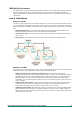
The following section illustrates how to use these ports to set up different applications.
In this application:
• Port 1 connects a single untagged device and assigns it to VLAN 5; it should be configured as an
Access Port with PVID 5.
• Port 2 connects a LAN with two untagged devices belonging to VLAN 2. One tagged device with VID 3
and one tagged device with VID 4. It should be configured as a Hybrid Port with PVID 2 for untagged
device and Fixed VLAN (Tagged) with 3 and 4 for tagged device. Since each port can only have one
unique PVID, all untagged devices on the same port must belong to the same VLAN.
• Port 3 connects with another switch. It should be configured as a Trunk Port. GVRP protocol will be
used through the Trunk Port.
• Port 4 connects a single untagged device and assigns it to VLAN 2; it should be configured as an
Access Port with PVID 2.
• Port 5 connects a single untagged device and assigns it to VLAN 3; it should be configured as an
Access Port with PVID 3.
• Port 6 connect a single untagged device and assigns it to VLAN 5; it should be configured as an Access
Port with PVID 5.
• Port 7 connects a single untagged device and assigns it to VLAN 4; it should be configured as an
Access Port with PVID 4.
After the application is properly configured:
• Packets from Device A will travel through Trunk Port 3 with tagged VID 5. Switch B will recognize its
VLAN, pass it to port 6, and then remove tags received successfully by Device G, and vice versa.
• Packets from Devices B and C will travel through Hybrid Port 2 with tagged VID 2. Switch B recognizes
its VLAN, passes it to port 4, and then removes tags received successfully by Device F, and vice versa.
• Packets from Device D will travel through Trunk Port 3 with tagged VID 3. Switch B will recognize its
VLAN, pass to port 5, and then remove tags received successfully by Device H. Packets from Device H
will travel through Trunk Port 3 with PVID 3. Switch A will recognize its VLAN and pass it to port 2, but
will not remove tags received successfully by Device D.
• Packets from Device E will travel through Trunk Port 3 with tagged VID 4. Switch B will recognize its
VLAN, pass it to port 7, and then remove tags received successfully by Device I. Packets from Device I
will travel through Trunk Port 3 with tagged VID 4. Switch A will recognize its VLAN and pass it to port
2, but will not remove tags received successfully by Device E.
VLAN Settings
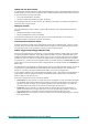
To configure VLAN, click VLAN on the function menu, then select IEEE 802.1Q. Click Global tab.
GVRP (Generic VLAN Registration Protocol) is an IEEE 802.1Q standard protocol that helps specify how to
define a method of tagging frames with VLAN configuration data. It essentially facilitates management of
VLAN within a larger network data communication.