
User Manual


Moxa’s Managed Switch Next Generation OS (v3.x) User Manual
97
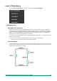
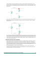
If STP is enabled, it will detect duplicate paths or block one of the paths from forwarding traffic. In the
following example, STP determined that traffic from segment 2 to segment 1 flows through switches C and
A since this path is in a forwarding state and is processing BPDUs. However, switch B on segment 1 is in a
blocking state.
What happens if a link failure is detected? As shown in the figure below, the STP will change the blocking
state to a forwarding state so that traffic from segment 2 flows through switch B to segment 1 through a
redundant path.
STP will determine which path between each segment is most efficient, and then assign a specific reference
point on the network. When the most efficient path has been identified, the other paths are blocked. In the
previous three figures, STP first determined that the path through switch C was the most efficient, and as a
result, blocked the path through switch B. After the failure of switch C, STP re-evaluated the situation and
opened the path through switch B.
Difference Between STP and RSTP
RSTP is similar to STP but includes additional information in the BPDUs that allow each bridge to confirm
that it has taken action to prevent loops from forming when it decides to enable a link to a neighboring
bridge. Adjacent bridges connected via point-to-point links will be able to enable a link without waiting to
ensure that all other bridges in the network have had time to react to the change. The main benefit of RSTP
is that the configuration decision is made locally rather than network-wide, allowing RSTP to carry out
automatic configuration and restore a link faster than STP.
STP and RSTP spanning tree protocols operate without regard to a network’s VLAN configuration and
maintain one common spanning tree throughout a bridged network. Thus, these protocols map one loop-
free, logical topology on a given physical topology.