MDS-G4000-4XGS/ MDS-G4000-L3-4XGS Series Quick Installation Guide Version 1.1, September 2022 Technical Support Contact Information www.moxa.com/support 2022 Moxa Inc. All rights reserved.
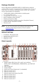
Package Checklist Moxa’s MDS-G4000-4XGS/MDS-G4000-L3-4XGS Series industrial modular DIN-rail switch is shipped with the following items. If any of these items are missing or damaged, please contact your customer service representative for assistance.
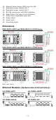
12. 13. 14. 15. 16. 17. 18. 19. 20. External Power Supply (EPS) input for PoE Redundant power module slot 1 Redundant power module slot 2 RS-232 console port with RJ45 interface Reset button (Pin hole 0.9 mm diameter) Relay output and Digital Input port Relay output Power input Grounding screw Dimensions MDS-G4012-4XGS and MDS-G4012-L3-4XGS Series MDS-G4020-4XGS and MDS-G4020-L3-4XGS Series MDS-G4028-4XGS and MDS-G4028-L3-4XGS Series Unit: mm (inch) Ethernet Modules (Hardware Rev.2.0.
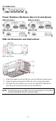
LM-7000H-4PoE Power Modules (Hardware Rev.2.1.0 and above) PWR-HV-P48-A PWR-LV-P48-A PWR-HV-NP PWR-LV-NP DIN-rail Dimension and Instructions Unit: mm (inch) 1. 2. 3. Insert the upper lip of the DIN rail into the DIN-rail mounting kit. Press the device towards the DIN rail until it snaps into place. Pull down the two latches one by one to release the DIN-rail kit and lift up to remove the device from the DIN rail.
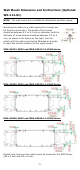
Wall Mount Dimension and Instructions (Optional: WK-112-01) NOTE The wall-mount kit is certified for Hazardous Location usage. Mounting the switch to a wall requires four screws per kit (there are two kits). The heads of the screws should be between 6.0 to 9.0 mm in diameter, and the diameter of screw thread should be between 3.5 to 4 mm, as shown in the figure on the right. Use the switch with the wall-mounting kit attached as a guide to mark the correct locations of the eight screws.
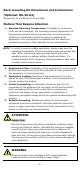
Rack-mounting Kit Dimensions and Instructions (Optional: RK-3U-02) Please refer to the RK-3U-02 Series QIG. Matters That Require Attention 1. Elevated Operating Temperature: If installed in a closed or multi-unit rack assembly, the operating ambient temperature of the rack environment may be greater than room temperature. Therefore, consideration should be given to installing the equipment in an environment compatible with the maximum ambient temperature (Tma) specified by the manufacturer. NOTE 2. 3.
Connecting the Power Inputs NOTE The required power module depends on the choice of LM-7000H module. Refer to the following power/module combination requirements. • • LM-7000H non-PoE modules: Any power module LM-7000H PoE modules: PWR-HV-P48-A, PWR-LV-P48-A only The MDS-G4000-4XGS/MDS-G4000-L3-4XGS Series supports 4 types of power supply: • • • • PWR-HV-P48-A: one 110/220 VAC/VDC (90 to 264 VAC, 88 to 300 VDC), one 48 VDC PoE power input for PoE+ ports.
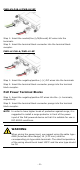
PWR-HV-P48-A/PWR-HV-NP Step 1: Insert the neutral/line (L/N/Ground) AC wires into the terminals. Step 2: Insert the terminal block connector into the terminal block receptor. PWR-LV-P48-A/PWR-LV-NP Step 1: Insert the negative/positive (-/+) DC wires into the terminals. Step 2: Insert the terminal block connector prongs into the terminal block receptor. PoE Power Terminal Blocks Step 1: Insert the negative/positive DC wires into the -/+ terminals, respectively.
NOTE When two power units are installed on the MDS-G40004XGS/MDS-G4000-L3-4XGS Series switch, both power units will be activated simultaneously, which will enable power redundancy. NOTE The reverse power input connection will not activate the device or PoE input. In addition, the PoE will only activate when the external power supply is installed on the same power unit. Wiring the Relay Contact Each power module has one relay output that can provide two types of relay output.
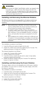
WARNING When wiring the Digital Input/Output contact, we suggest using the cable type - AWG (American Wire Gauge) 16-28 (1.310.081 mm2) and the corresponding pin type cable terminals. The rated temperature of the wiring should be at least 105°C and the wire type should be CU. Installing and Removing the Ethernet Modules The Ethernet modules are hot-swappable for the same module type. You can mount or remove the Ethernet module while the device is operating. NOTE 1. 2. 3.
3. 4. Insert the dummy module into the slot in order to have better protection against dust and EMI. Fasten the dummy module using the 2 screws. The tightening torque is 4 kgf-cm (0.4 Nm) NOTE If one of the modules is removed from the device, it is recommended to insert a dummy module in order to provide better protection against dust and EMI. Grounding the Moxa Industrial DIN-rail Switch Grounding and wire routing help limit the effects of noise due to electromagnetic interference (EMI).
3 4 D+ (Data+) GND (Ground) The Reset Button (diameter 0.9 mm) The reset button can perform two functions. One is to reset the switch to factory default settings and the other is to reboot the switch if the button has been depressed and release immediately. Resetting to Factory Default Settings Depress the Reset button for five seconds to load the factory default settings. Use a pointed object, such as a straightened paper clip or needle (the diameter must not exceed 0.9 mm), to depress the Reset button.
LED Color Amber SYNC Green System LEDs (Except PWR) Green/ Amber/ Red State On Blinking Off Description The PTP function is enabled. The switch is receiving sync packets. The PTP function is disabled. The PTP function has successfully On converged. The switch is being discovered/located by the locator Blinking function. The System LED includes the STA, FLT, M/H, C/T, and SYNC LEDs.
LM-7000H-4GTX/LM-7000H-4GSFP/LM-7000H-4TX LED Color Green MS (Module State) Red State On Blinking Off On On Green Blinking Off Copper (10/100 Mbps) On Amber Blinking Off On Green Blinking Off Copper (10/100/ 1000 Mbps) On Amber Blinking Off On Green Blinking Off SFP (100/1000 Mbps) On Amber Blinking Off Description Normal operation. The module is booting up. The module is out of service. 1. The module initialization has failed, or 2. A module designed for a different model was inserted.
LM-7000H-4GPoE/LM-7000H-4PoE LED Color State On Green Blinking Off On Description Normal operation. The module is booting up. This module is out of service. 1. The module failed to initialize. 2. A user inserted a module designed for a different model. 3. When performing a cold start, the module was removed and inserted before initialization was complete. Normal operation. Off No external power supply for PoE.
PWR-HV-P48-A/PWR-LV-P48-A LED Color EPS (External Amber Power Supply) State On Off On PWR Amber Off Description External power is being supplied to the module's EPS input. No external power supply. Power is being supplied to the module's power input. Power is not being supplied to the module's power input. PWR-HV-NP/PWR-LV-NP LED Color State On PWR Amber Off Description Power is being supplied to the module's power input. Power is not being supplied to the module's power input.
Input Current When using PWR-HV-P48-A/PWR-HV-NP: (without modules 110 VDC: 0.11 A 220 VDC: 0.06 A consumption) 110 VAC: 0.29 A 220 VAC: 0.18 A When using PWR-LV-P48-A/PWR-LV-NP: 24 VDC: 0.53 A 48 VDC: 0.28 A Peak Inrush PWR-HV-P48-A/PWR-HV-NP: Current 110 VAC: < 10 A (t > 0.1 ms) 220 VAC: < 20 A (t > 0.1 ms) PWR-LV-P48-A/PWR-LV-NP: 24 VDC: < 5 A (t > 0.1 ms) 48 VDC: < 10 A (t > 0.1 ms) Maximum PoE 36 W Power Output per Port Total PoE Power Max.
Weight MDS-G4012-4XGS-T/MDS-G4012-L3-4XGS-T Series: 3.03 kg (6.68 lb) MDS-G4020-4XGS-T/MDS-G4020-L3-4XGS-T Series: 3.40 kg (7.50 lb) MDS-G4028-4XGS-T/MDS-G4028-L3-4XGS-T Series: 3.79 kg (8.36 lb) LM-7000H-4GSFP: 0.30 kg (0.66 lb) LM-7000H-4GTX: 0.24 kg (0.53 lb) LM-7000H-4GPoE: 0.31 kg (0.69 lb) LM-7000H-4TX: 0.24 kg (0.53 lb) LM-7000H-4PoE: 0.31 kg (0.69 lb) PWR-HV-P48-A: 0.42 kg (0.93 lb) PWR-LV-P48-A: 0.40 kg (0.88 lb) PWR-HV-NP/PWR-LV-NP: 0.34 kg (0.
ATTENTION • • • • • NOTE • • • This device is an open-type equipment and should be installed in a suitable enclosure. Please use an optical transceiver (SFP) that complies with IEC 60825-1, 21 CFR 1040 Section 1040.10 and 1040.11, classified as Class 1 laser product. If the equipment is used in a manner not specified by the manufacturer, the protection provided by the equipment may be impaired.