MDS-G4000/MDS-G4000-L3 Series Quick Installation Guide Version 1.4, August 2022 Technical Support Contact Information www.moxa.com/support 2022 Moxa Inc. All rights reserved.
Package Checklist Moxa’s MDS-G4000/MDS-G4000-L3 Series industrial modular DIN-rail switch is shipped with the following items. If any of these items are missing or damaged, please contact your customer service representative for assistance.
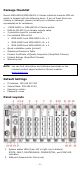
. 4. 5. 6. 7. 8. 9. 10. 11. 12. 13. 14. 15. 16. 17. 18. 19. 20.
Ethernet Modules (Hardware Rev.2.0.0 and above) NOTE Transceivers for the LM-7000H-4GSFP module are sold separately. Refer to Supported SFP Modules for list of supported transceivers. LM-7000H-4GTX LM-7000H-4GSFP LM-7000H-4GPoE LM-7000H-4TX LM-7000H-4PoE Power Modules (Hardware Rev.2.1.0 and above) NOTE The PWR-LV-P48 power module is certified for Hazardous Location use.
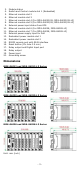
MDS-G4020/28 and MDS-G4020/28-L3 Series 1. Insert the upper lip of the DIN rail into the DIN-rail mounting kit. 2. Press the device towards the DIN rail until it snaps into place. 3. Pull down the two latches one by one to release the DIN-rail kit and lift up to remove the device from the DIN rail. NOTE The DIN rail must use the TS35 (15 mm) specification. Wall-mounting Dimensions and Instructions (Optional: WK-112-01) NOTE The wall-mount kit is certified for Hazardous Location usage.
Rack-mounting Dimensions and Instructions (Optional: RK-3U-02) Please refer to the RK-3U-02 Series QIG. Matters That Require Attention 1. Elevated Operating Temperature: If installed in a closed or multi-unit rack assembly, the operating ambient temperature of the rack environment may be greater than room temperature. Therefore, consideration should be given to installing the equipment in an environment compatible with the maximum ambient temperature (Tma) specified by the manufacturer. NOTE 2.
ATTENTION Safety First! Be sure to disconnect the power cord before installing and/or wiring your Ethernet Switch. Calculate the maximum possible current in each power wire and common wire. Observe all electrical codes dictating the maximum current allowable for each wire size. If the current goes above the maximum ratings, the wiring could overheat, which can cause serious damage to your equipment.
ATTENTION For Hazardous Location Use The PoE capacity of the PWR-LV-P48 is only certified for use in hazardous locations up to a maximum power budget of 369.6 W and a maximum output of up to 15.4 W per port. For the PWR-HV-NP, the 110/220 VAC/VDC power supplies provide power to the switch. For the PWR-LV-NP, the 24/48 VDC power supplies provide power to the switch. Power Terminal Blocks The connection for power input and PoE external power supply is on the power modules. PWR-HV-P48/PWR-HV-NP 1. 2.
PoE Power Terminal Blocks 1. 2. 3. 4. 5. Remove 8 to 9 mm of the DC wires’ protective cover. Use a tool to push the spring mechanism inwards to open it. Insert the negative/positive (-/+) DC wires into the terminals. Release the spring mechanism. Insert the terminal block connector prongs into the terminal block receptor.
FAULT: The relay contact of the 3-pin terminal block connector is used to detect user-configured events. The module provides normally open and normally closed circuits depending on what the user chooses. For pin definitions refer to the table below.
NOTE The default module is 4GTX, if it is the first time you are mounting a 4TX, PoE, or SFP module, please reboot the switch after inserting it. The hot-swappable function, as defined above, will only work after the device is rebooted for the first time. NOTE If a different model type module is changed on the same slot, it is recommended to reconfigure the settings or reset the device to default settings after rebooting the switch. To install an Ethernet module: 1. 2.
NOTE Using a shielded cable achieves better electromagnetic resistance. NOTE When grounding, we suggest using the cable type - AWG (American Wire Gauge) 16 (1.31 mm2). RS-232 with RJ45 Interface Console Connection The switch has an RS-232 serial console with an RJ45 interface. Use a Moxa 9-pin female console cable to connect to your PC's COM port (or via USB-to-Serial converters or hubs).
LED Indicators The function of each LED is described in the table below. LED Color STA (STATE) Green Red FLT (FAULT) Red M/H (MSTR/ HEAD) Green C/T (CPRL/TAIL) Green SYNC (Reserved) Amber Green System LED (Except PWR) Green/ Amber/ Red State Description System LEDs On Normal operation. Blinking 1. The system is booting up. Off N/A On The system failed to initialize. 1. Switch failed to initialize. On 2. EEPROM information error.
SWC-4GTX LED MS (Module State) Color Green Red Green Copper (10/100/ 1000Mbps) Amber State On Blinking Off Description Normal operation. This module is booting up. The module is out of service. 1. The module failed to initialize. On 2. A module designed for a different model was inserted. When the port is active and links on On 1,000 Mbps. When the port’s data is being Blinking transmitted at 1,000 Mbps. When the port is inactive or link Off down. When the port is active and links on On 10/100 Mbps.
LM-7000H-4GTX/LM-7000H-4GSFP/LM-7000H-4TX LED MS (Module State) Color Green Red State On Blinking Off On On Green Blinking Off Copper (10/100 Mbps) On Amber Blinking Off On Green Blinking Off Copper (10/100/ 1000Mbps) On Amber Blinking Off On Green Blinking Off SFP (100/1000 Mbps) On Amber Blinking Off Description Normal operation. This module is booting up. The module is out of service. 1. The module failed to initialize. 2. A module designed for a different model was inserted.
LM-7000H-4GPoE/LM-7000H-4PoE LED Color State On Green Blinking Off On Description Normal operation. The module is booting up. This module is out of service. 1. The module failed to initialize. 2. A user inserted a module designed for a different model. 3. When performing a cold start, the module was removed and inserted before initialization was complete. Normal operation. Off No external power supply for PoE.
PWR-HV-P48/PWR-LV-P48 LED Color EPS (External Amber Power Supply) State On Off On PWR Amber Off Description External power is being supplied to the module's EPS input. No external power supply for PoE. Power is being supplied to the module's power input. Power is not being supplied to the module's power input. PWR-HV-NP/PWR-LV-NP LED Color State On PWR Amber Off Description Power is being supplied to the module's power input. Power is not being supplied to the module's power input.
Power Consumption (without modules consumption) Power Consumption of module Input Current (without modules consumption) Peak Inrush Current Maximum PoE Power Output per Port Total PoE Power Budget When using PWR-HV-P48: 110 VDC: 12.43 W 220 VDC: 12.87 W 110 VAC: 13.42 W 220 VAC: 14.08 W When using PWR-LV-P48: 24 VDC: 12.67 W 48 VDC: 13.2 W LM-7000H-4GTX: 3.63 W LM-7000H-4GPoE: 3.8 W LM-7000H-4GSFP: 4.8 W LM-7000H-4TX: 1.85 W LM-7000H-4PoE: 1.85 W When using PWR-HV-P48/PWR-HV-NP: 110 VDC: 0.
Weight MDS-G4012/MDS-G4012-L3 Series: 2.00 kg (4.41 lb) MDS-G4020/MDS-G4020-L3 Series: 2.50 kg (5.51 lb) MDS-G4028/MDS-G4028-L3 Series: 2.84 kg (6.26 lb) LM-7000H-4GSFP: 0.3 kg (0.66 lb) LM-7000H-4GTX: 0.24 kg (0.53 lb) LM-7000H-4GPoE: 0.31 kg (0.69 lb) LM-7000H-4TX: 0.24 kg (0.53 lb) LM-7000H-4PoE: 0.31 kg (0.69 lb) PWR-HV-P48/PWR-LV-P48: 0.36 kg (0.69 lb) PWR-HV-NP/PWR-LV-NP: 0.34 kg (0.
Warranty Warranty Period 5 years Details See www.moxa.
Module SFP-1G40ALC-T Description WDM-type (BiDi) SFP module with 1 1000BaseSFP port with LC connector for 40 km transmission; TX 1310 nm, RX 1550 nm, -40 to 85°C operating temperature SFP-1G40BLC WDM-type (BiDi) SFP module with 1 1000BaseSFP port with LC connector for 40 km transmission; TX 1550 nm, RX 1310 nm, 0 to 60°C operating temperature SFP-1G40BLC-T WDM-type (BiDi) SFP module with 1 1000BaseSFP port with LC connector for 40 km transmission; TX 1550 nm, RX 1310 nm, -40 to 85°C operating temperature S
Module SFP-1GTXRJ45-T Description SFP module with 1 1000BaseT port with RJ45 connector for 100 m transmission, -40 to 75°C operating temperature Note: This module is not certified for Hazardous Location. Restricted Access Locations • • This equipment is intended to be used in Restricted Access Locations, such as a computer room, with access limited to service personnel or users who have been instructed on how to handle the metal chassis of equipment that is very hot.
Hazardous Location Usage Terms Usage Terms Models Rating MDS-G4012, MDS-G4012-T MDS-G4020, MDS-G4020-T MDS-G4028, MDS-G4028-T Input: 24 to 48 VDC, 3.3 A (for PWR input) and 48 VDC, 8.2 A (for EPS input) Relay Output: 30 VDC/1 A Digital Input: 30 VDC/8 mA PoE Output: 48 VDC, 15.4 W per port ≧105°C Conductors suitable for rated cable temperature Hazardous EN IEC 60079-0:2018 Location EN IEC 60079-7:2015+A1:2018 EN IEC 60079-15: 2019 Class I, Division 2, Groups A, B, C, and D Address of No. 1111, Heping Rd.