
User Manual


- 4 -
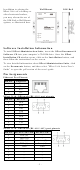
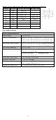
LED Indicators—NPort 5100’s top panel has three LED indicators, which
are described in the following table.
LED Name
LED Color
LED Function
Ready
Red
Steady on: Power is on and NPort is booting up.
Blinking: Indicates an IP conflict, or DHCP or
BOOTP server is not responding properly.
Green
Steady on: Power is on and NPort is functioning
normally.
Blinking: The NPort has been located by NPort
Administrator’s Location function
Off
Power is off, or power error condition exists.
Link
Orange
10 Mbps Ethernet connection.
Green
100 Mbps Ethernet connection.
Off
Ethernet cable is disconnected, or has a short.
Tx/Rx
Orange
Serial port is receiving data.
Green
Serial port is transmitting data.
Off
No data is being transmitted or received through
the serial port.
Adjustable pull high/low resistor for RS-422/485 (150
KΩ or 1 KΩ)
Jumpers are used to set the pull high/low
resistor values. The default is 150 KΩ.
Short the
jumpers to set this value to 1
KΩ. Do not use the KΩ setting with
RS
-
232 mode, since doing so will degrade
the RS
-232 signals and shorten the
communication distance.
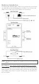
Hardware Installation Information
STEP 1: After removing the NPort 5100 series device server from the box,
connect the NPort 5100 series device server to a network. Use a standard
straight-through Ethernet cable to connect to a hub or switch. When
setting up or testing the NPort 5100 series device server, you might find
it convenient to connect directly to your computer’s Ethernet port. In this
case, use a cross-over Ethernet cable.
STEP 2: Connect the NPort 5100 series device server’s serial port to a
serial device.
STEP 3: Connect the power adaptor.
STEP 4: Placement options