NPort 5000AI-M12 Series User Manual First Edition, June 2012 www.moxa.com/product © 2012 Moxa Inc. All rights reserved. Reproduction without permission is prohibited.
NPort 5000AI-M12 Series User Manual The software described in this manual is furnished under a license agreement and may be used only in accordance with the terms of that agreement. Copyright Notice Copyright ©2012 Moxa Inc. All rights reserved. Reproduction without permission is prohibited. Trademarks The MOXA logo is a registered trademark of Moxa Inc. All other trademarks or registered marks in this manual belong to their respective manufacturers.
Table of Contents 1. Introduction ...................................................................................................................................... 1-1 Overview ........................................................................................................................................... 1-2 Package Checklist ............................................................................................................................... 1-2 Product Features ..................
6. Configuring NPort Administrator ....................................................................................................... 6-1 Overview ........................................................................................................................................... 6-2 Installing NPort Administrator .............................................................................................................. 6-2 Configuration .......................................................
1 1. Introduction Welcome to the NPort 5000AI-M12 Series of industrial serial device servers. There are a total of nine models in this series and they will be referred to collectively as the “NPort 5000AI-M12 Series” in this manual.
NPort 5000AI-M12 Series Introduction Overview NPort 5000AI-M12 device server is designed to make serial devices network-ready in an instant and is compliant with EN 50155 and EN 50121-4 standards, allowing them to perform reliably in rolling stock and wayside applications where high level vibration is present. Use the NPort 5000AI-M12 device servers to give your PC software direct access to serial devices from anywhere on the network.
NPort 5000AI-M12 Series Introduction Stop Bits: 1, 1.5, 2 Parity: None, Even, Odd, Space, Mark Flow Control: RTS/CTS and DTR/DSR (RS-232 only), XON/XOFF Baudrate: 50 to 921.
NPort 5000AI-M12 Series Introduction MTBF (mean time between failures): NPort 5150AI-M12: 789,341 hrs NPort 5250AI-M12: 639,622 hrs NPort 5450AI-M12: 467,777 hrs Warranty Warranty Period: 5 years Details: See www.moxa.
2 2. Getting Started In this chapter, we give instructions on installing NPort 5000AI-M12 device servers. Software installation is covered in subsequent chapters.
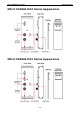
NPort 5000AI-M12 Series Getting Started NPort 5150AI-M12 Series Appearance NPort 5250AI-M12 Series Appearance 2-2
NPort 5000AI-M12 Series Getting Started NPort 5450AI-M12 Series Appearance Connecting the Hardware This section describes how to connect NPort 5000AI-M12 to serial devices for first time testing purposes. We cover Wiring Requirements, Connecting the Power, Connecting to the Network, Connecting to a Serial Device, and LED Indicators. Wiring Requirements ATTENTION Safety First! Be sure to disconnect the power cord before installing and/or wiring your NPort 5000AI-M12 Series.
NPort 5000AI-M12 Series Getting Started You should observe the following: • Use separate paths to route wiring for power and devices. If power wiring and device wiring paths must cross, make sure the wires are perpendicular at the intersection point. NOTE: Do not run signal or communication wiring and power wiring in the same wire conduit. To avoid interference, wires with different signal characteristics should be routed separately.
NPort 5000AI-M12 Series Getting Started STEP 2: Position the NPort 5000AI-M12 on the DIN-Rail, tilting to hook clamps over the top edge of the rail. STEP 3: Swing the device server down fully onto the DIN-Rail until both clamps completely latch. Connecting the Power Connect the power line with the NPort 5000AI-M12’s M12 connector. If the power is properly supplied, the “Ready” LED will show a solid red color until the system is ready, at which time the “Ready” LED will change to a green color.
NPort 5000AI-M12 Series Getting Started Connecting to a Serial Device Connect the serial data cable between NPort 5000AI-M12 and the serial device. Serial data cables are optional accessories for NPort. LED Indicators The top panels of all NPort 5000AI-M12 have four LED indicators, as described in the following table. Name Color PWR green red Ready green off 10M, 100M P1, P2, P3, P4 Function Power is being supplied to the power input. Steady on: Power is on and NPort is booting up.
3 3. Initial IP Address Configuration When setting up your NPort 5000AI-M12 for the first time, the first thing you should do is configure the IP address. This chapter introduces the methods that can be used to configure the device server’s IP address. Select one of the initial IP Address configuration methods to configure NPort 5000AI-M12’s IP Address. For more details about network settings, see the Network Settings section from Chapter 5, Web Console Configuration.
NPort 5000AI-M12 Series Initial IP Address Configuration Initializing the NPort’s IP Address 1. Determine whether your NPort 5000AI-M12 needs to use a Static IP or Dynamic IP (either DHCP or BOOTP application). 2. If the NPort 5000AI-M12 is used in a Static IP environment, you can use NPort Administration Suite, ARP, Web Console, Telnet Console, or Serial Console to configure the new IP address. 3.
NPort 5000AI-M12 Series Initial IP Address Configuration Take the following steps to use ARP to configure the IP address: 1. Obtain a valid IP address for your NPort 5000AI-M12 from your network administrator. 2. Obtain the NPort 5000AI-M12’s MAC address from the label on its bottom panel. 3. Execute the ‘arp -s’ command from your computer’s MS-DOS prompt by typing: arp –s 192.168.200.100 00-90-E8-xx-xx-xx This is where 192.168.200.
NPort 5000AI-M12 Series Initial IP Address Configuration 4. Type 2 to select Network settings, and then press Enter. 5. Type 1 to select IP address and then press Enter. 6. Use the Backspace key to erase the current IP address, type in the new IP address, and then press Enter.
NPort 5000AI-M12 Series Initial IP Address Configuration 7. Press any key to continue… 8. Type m and then press Enter to return to the main menu. 9. Type s and then press Enter to Save/Restart the system.
NPort 5000AI-M12 Series Initial IP Address Configuration 10. Type y and then press Enter to save the new IP address and restart the NPort 5000AI-M12. Serial Console (19200, n, 8, 1) You may use the RS-232 console port to set up the IP address for NPort 5000AI-M12. We suggest using PComm Terminal Emulator, which is available free of charge as part of the PComm Lite program suite, to carry out the installation procedure, although other similar utilities may also be used.
NPort 5000AI-M12 Series Initial IP Address Configuration 7. The NPort 5000AI-M12 will automatically switch from data mode to console mode as it receives a continuous string of “ ` ” characters. 8. Input the password when prompted. Note that this page will only appear when the NPort 5000AI-M12 has been set up for password protection. 9. Start configuring the IP address under Network Settings. Refer to step 4 in the Telnet Console section for the rest of the IP settings.
4 4. Choosing the Proper Operation Mode In this chapter, we describe the various NPort 5000AI-M12 operation modes. The options include an operation mode that uses a driver installed on the host computer, and operation modes that rely on TCP/IP socket programming concepts. After choosing the proper operation mode in this chapter, refer to Chapter 5 for detailed configuration parameter definitions.
NPort 5000AI-M12 Series Choosing the Proper Operation Mode Overview NPort 5000AI-M12 Serial Device Servers network-enable traditional RS-232/422/485 devices, in which a Serial Device Server is a tiny computer equipped with a CPU, real-time OS, and TCP/IP protocols that can bi-directionally translate data between the serial and Ethernet formats. Your computer can access, manage, and configure remote facilities and equipment over the Internet from anywhere in the world.
NPort 5000AI-M12 Series Choosing the Proper Operation Mode ATTENTION Real COM Mode allows several hosts to have access control over the same NPort 5000AI-M12. The driver that comes with your NPort 5000AI-M12 controls host access to attached serial devices by checking the host’s IP address. Refer to Accessible IP Settings in Chapter 5 for more details.
NPort 5000AI-M12 Series Choosing the Proper Operation Mode UDP Mode Compared to TCP communication, UDP is faster and more efficient. In UDP mode, you can not only unicast but also multicast data from the serial device to multiple host computers, and the serial device can also receive data from multiple host computers, making this mode ideal for message display applications.
NPort 5000AI-M12 Series Choosing the Proper Operation Mode Reverse Telnet Mode Console management is commonly used by connecting to Console/AUX or COM ports of routers, switches, and UPS units. Rtelnet works the same as RAW mode in that only one TCP port is listened to after booting up. The system then waits for a host on the network to initiate a connection. The difference is that the RAW mode does not provide the conversion function provided by Telnet.
5 5. Web Console Configuration The Web Console is the most user-friendly of the methods available to configure the NPort 5000AI-M12. In this chapter, we introduce the Web Console function groups and function definitions.
NPort 5000AI-M12 Series Web Console Configuration Opening Your Browser 1. Make sure your browser has cookies enabled. To enable cookies in Internet Explorer, right click on the Internet Explorer icon on your desktop, select Properties, click on the Security tab, and then select Enable under Allow cookies that are stored on your computer, Allow per-session cookies (not stored), and File download. 2. Enter the IP address of your device in the address field of the browser, then press the Enter key.
NPort 5000AI-M12 Series Web Console Configuration 4. The NPort 5000AI-M12 homepage will open next. There are two buttons on this page: Quick setup and Export/Import. You can click Overview at any time to go back to this page. The following sections introduce these two convenient functions and all the other specific settings in the Main Menu on the left.
NPort 5000AI-M12 Series Web Console Configuration In Step 1/3, you must assign a valid IP address to the NPort 5000AI-M12 before it will work in your network environment. Your network system administrator should provide you with an IP address and related settings for your network. In addition, the server name field is a useful way to specify the location or application of different NPort 5000AI-M12s. In the Step 2/3, you must specify which operation mode you will use.
NPort 5000AI-M12 Series Web Console Configuration In the Step 3/3, you can modify the serial settings. Review your settings at the Finish Settings page to confirm that they are correct, and then click the Save/Restart button to restart the device with the new settings. Note that if you changed the IP address, you will not be able to return to the Home Page with the Home button.
NPort 5000AI-M12 Series Web Console Configuration Export/Import Export/Import allows you to back up and recover your settings. Click Export to store all configuration data into a default file, .txt. Click the Import button to upload a configuration file to the NPort 5000AI-M12. Basic Settings Server name Setting Factory Default Necessity 1 to 39 characters NP[model name]_[Serial No.
NPort 5000AI-M12 Series Web Console Configuration Telnet console Setting Factory Default Necessity Enable or Disable Enable Required ATTENTION If you disable both the “Web console” and “Telnet console,” you can still use NPort Administrator to configure NPort 5000AI-M12 device servers locally or remotely over the network. Refer to Chapter 6 for more details.
NPort 5000AI-M12 Series Web Console Configuration IP address Setting Factory Default Necessity E.g., 192.168.1.1 (IP 192.168.127.254 Required addresses of the form x.x.x.0 and x.x.x.255 are invalid.) An IP address is a number assigned to a network device (such as a computer) as a permanent address on the network. Computers use the IP address to identify and talk to each other over the network. Choose a proper IP address which is unique and valid in your network environment.
NPort 5000AI-M12 Series Web Console Configuration DNS server 2 configuration items to configure the IP address of the DNS server. DNS Server 2 is included for use when DNS sever 1 is unavailable. NPort 5000AI-M12 plays the role of DNS client, in the sense that the NPort 5000AI-M12 will actively query the DNS server for the IP address associated with a particular domain name.
NPort 5000AI-M12 Series Web Console Configuration Auto report to TCP port Setting Factory Default Necessity E.g., 4001 4002 Optional Setting Factory Default Necessity Time interval (in 10 Optional Auto report period seconds) LLDP Settings This section is used to configure the setting of LLDP protocol, The LLDP (Link Layer Discovery Protocol) may be used as a component in network management and monitoring applications.
NPort 5000AI-M12 Series Web Console Configuration Port alias Setting Factory Default Necessity 1 to 15 characters None Optional (E.g., PLC-No.1) “Port alias” is included to allow easy identification of the serial devices that are connected to the NPort 5000AI-M12’s serial ports. Serial Parameters ATTENTION Check the serial communication parameters in your serial device’s user’s manual.
NPort 5000AI-M12 Series Web Console Configuration Flow control Setting Factory Default Necessity None, RTS/CTS, RTS/CTS Required DTR/DSR, Xon/Xoff FIFO Setting Factory Default Necessity Enable, Disable Enable Required The NPort 5000AI-M12’s serial ports provide a 16-byte FIFO in both the Tx and Rx directions. To prevent unexpected communication, disable the FIFO setting when your serial device does not have a FIFO.
NPort 5000AI-M12 Series Web Console Configuration Real COM Mode TCP alive check time Setting Factory Default Necessity 0 to 99 min 7 min Optional 0 min: The TCP connection will not be closed due to an idle TCP connection. 1 to 99 min: NPort 5000AI-M12 automatically closes the TCP connection if there is no TCP activity for the given time. After the connection is closed, the NPort 5000AI-M12 starts listening for another Real COM driver connection from another host.
NPort 5000AI-M12 Series Web Console Configuration ATTENTION When “Max connection” is set greater than 1, this means that the NPort 5000AI-M12 will be using a “multi connection application” (i.e., Up to 8 hosts are allowed access to the port at the same time). When using a multi connection application, the NPort 5000AI-M12 will use the serial communication parameters set in the console. All of the hosts connected to that port must use the same serial settings.
NPort 5000AI-M12 Series Web Console Configuration Do nothing, Delimiter + Do Nothing Optional 1, Delimiter + 2, Strip Delimiter Delimiter + 1 or Delimiter + 2: The data will be transmitted when an additional byte (for Delimiter +1), or an additional 2 bytes (for Delimiter +2) of data is received after receiving the Delimiter. Strip Delimiter: When the Delimiter is received, the Delimiter is deleted (i.e., stripped), and the remaining data is transmitted.
NPort 5000AI-M12 Series Web Console Configuration RFC2217 Mode TCP alive check time Setting Factory Default Necessity 0 to 99 min 7 min Optional 0 min: TCP connection is not closed due to an idle TCP connection. 1 to 99 min: The NPort 5000AI-M12 automatically closes the TCP connection if there is no TCP activity for the given time. After the connection is closed, the NPort 5000AI-M12 starts listening for another host’s TCP connection.
NPort 5000AI-M12 Series Web Console Configuration Once the NPort 5000AI-M12 receives both delimiters through its serial port, it immediately packs all data currently in its buffer and sends it out the NPort 5000AI-M12’s Ethernet port.
NPort 5000AI-M12 Series Web Console Configuration TCP Server Mode TCP alive check time Setting Factory Default Necessity 0 to 99 min 7 min Optional 0 min: The TCP connection will not be closed due to an idle TCP connection. 1 to 99 min: The NPort 5000AI-M12 automatically closes the TCP connection if there is no TCP activity for the given time. After the connection is closed, the NPort 5000AI-M12 starts listening for another host’s TCP connection.
NPort 5000AI-M12 Series Web Console Configuration ATTENTION The Inactivity time should be configured to be larger than the Force transmit timeout setting. To prevent the unintended loss of data due to the session disconnection, it is highly recommended that you set this value large enough so that the intended data transfer is completed.
NPort 5000AI-M12 Series Web Console Configuration ATTENTION Delimiter 2 is optional. If left blank, then Delimiter 1 alone trips clearing of the buffer. If the size of the serial data received is greater than 1 KB, the NPort 5000AI-M12 will automatically pack the data and send it to the Ethernet. However, to use the delimiter function, you must at least enable Delimiter 1. If Delimiter 1 is left blank and Delimiter 2 is enabled, the delimiter function will not work properly.
NPort 5000AI-M12 Series 1 to 65535 Web Console Configuration 966 Optional The Command port is a listen TCP port for IP-Serial Lib commands from the host. In order to prevent a TCP port conflict with other applications, the user can set the Command port to another port if needed. IP-Serial Lib will automatically check the Command Port on NPort 5000AI-M12 so that the user does not need to configure the program.
NPort 5000AI-M12 Series Web Console Configuration 1-65535 ms: NPort 5000AI-M12 automatically closes the TCP connection if there is no serial data activity for the given time. This parameter defines the maintenance status as Closed or Listen for the TCP connection. The connection is closed if there is no incoming or outgoing data through the serial port during the specific Inactivity time.
NPort 5000AI-M12 Series Web Console Configuration Delimiter + 1 or Delimiter + 2: The data will be transmitted when an additional byte (for Delimiter +1), or an additional 2 bytes (for Delimiter +2) of data is received after receiving the Delimiter. Strip Delimiter: When the Delimiter is received, the Delimiter is deleted (i.e., stripped), and the remaining data is transmitted. Do Nothing: The data will be transmitted when the Delimiter is received.
NPort 5000AI-M12 Series Web Console Configuration Designated Local Port 1/2/3/4 Setting Factory Default Necessity TCP Port No. 5011 (Port 1) Required 5012 (Port 2) 5013 (Port 3) 5014 (Port 4) Connection control Setting Factory Default Necessity Startup/None, Any Character/None, Startup/None Required Any Character/Inactivity Time, DSR ON/DSR OFF, DSR ON/None, DCD ON/DCD OFF, DCD ON/None The meaning of each of the above settings is given in the table below.
NPort 5000AI-M12 Series Web Console Configuration UDP Mode Packing length Setting Factory Default Necessity 0 to 1024 0 Optional Default = 0, The Delimiter Process will be followed, regardless of the length of the data packet. If the data length (in bytes) matches the configured value, the data will be forced out. The data length can be configured for 0 to 1024 bytes. Set to 0 if you do not need to limit the length.
NPort 5000AI-M12 Series Web Console Configuration Delimiter + 1 or Delimiter + 2: The data will be transmitted when an additional byte (for Delimiter +1), or an additional 2 bytes (for Delimiter +2) of data is received after receiving the Delimiter. Strip Delimiter: When the Delimiter is received, the Delimiter is deleted (i.e., stripped), and the remaining data is transmitted. Do Nothing: The data will be transmitted when the Delimiter is received.
NPort 5000AI-M12 Series Web Console Configuration Management Protocol (IGMP) is used to communicate group membership information between hosts and routers on a LAN. The NPort 5000AI-M12 supports IGMP version 2. To add a network host to the multicast group, input the host’s IP address (e.g., 239.1.1.1) in one of the Destination IP address input boxes, as illustrated above.
NPort 5000AI-M12 Series Web Console Configuration TCP alive check time Setting Factory Default Necessity 0 to 99 min 7 min Required 0 min: TCP connection is not closed due to an idle TCP connection. 1 to 99 min: The NPort 5000AI-M12 closes the TCP connection automatically if there is no TCP activity for the given time. Destination IP address Setting Factory Default Necessity IP address or Domain Name blank Optional 4001 Required (E.g., 192.168.1.1) TCP port No.
NPort 5000AI-M12 Series Web Console Configuration Ethernet Modem Mode Dial-in The NPort 5000AI-M12 listens for a TCP/IP connection request from the remote Ethernet modem or host. The NPort 5000AI-M12’s response depends on the ATS0 value, as outlined below. ATS0=0 (default): The NPort 5000AI-M12 will temporarily accept the TCP connection and then send the “RING” signal out through the serial port. The serial controller must reply with “ATA” within 2.
NPort 5000AI-M12 Series Web Console Configuration AT Commands The NPort 5000AI-M12 supports the following common AT commands used with a typical modem: No. AT command Description 1 ATA Answer manually 2 ATD : Dial up the IP address: Port No.
NPort 5000AI-M12 Series Web Console Configuration 9 S8 Pause time for dial delay (always=2, unit=sec) no action applied 10 S9 Carrier detect response time (always=6, unit 1/10 sec) no action applied 11 S10 Delay for hang up after carrier no action applied (always=14, unit 1/10 sec) 12 S11 DTMF duration and spacing (always=100 ms) 13 S12 Escape code guard time no action applied (default=50, unit 1/50 sec) to control the idle time for “+++” TCP alive check time Setting Factory Default N
NPort 5000AI-M12 Series Web Console Configuration 1-65535 ms: The NPort 5000AI-M12 automatically closes the TCP connection if there is no serial data activity for the given time. After the connection is closed, the NPort 5000AI-M12 starts listening for another host’s TCP connection. This parameter defines the maintenance status as Closed or Listen for the TCP connection. The connection is closed if there is no incoming or outgoing data through the serial port during the specific Inactivity time.
NPort 5000AI-M12 Series Web Console Configuration Accessible IP Settings The NPort 5000AI-M12 uses an IP address based filtering method to control access to itself. Accessible IP Settings allows you to add or block remote host IP addresses to prevent unauthorized access. Access to the NPort 5000AI-M12 is controlled by IP address. That is, if a host’s IP address is in the accessible IP table, then the host will be allowed to access the NPort 5000AI-M12.
NPort 5000AI-M12 Series Web Console Configuration Auto Warning Settings Auto warning: Email and SNMP trap Mail Server Mail server Setting Factory Default Necessity IP Address or Domain None Optional Name User name Setting Factory Default Necessity 1 to 15 characters None Optional Password Setting Factory Default Necessity 1 to 15 characters None Optional Setting Factory Default Necessity 1 to 63 characters None Optional From E-mail address E-mail address 1/2/3/4 Setting Factory
NPort 5000AI-M12 Series Web Console Configuration ATTENTION Consult your Network Administrator or ISP for the proper mail server settings. The Auto warning function may not work properly if it is not configured correctly. the NPort 5000AI-M12 SMTP AUTH supports LOGIN, PLAIN, CRAM-MD5 (RFC 2554).
NPort 5000AI-M12 Series Web Console Configuration Authentication failure The user inputs a wrong password from the Console or Administrator. When authentication failure occurs, the NPort will immediately send an e-mail or send an SNMP trap. IP address changed The user has changed the NPort 5000AI-M12’s IP address. When the IP address changes, the NPort 5000AI-M12 will send an e-mail with the new IP address before the NPort 5000AI-M12 reboots.
NPort 5000AI-M12 Series Web Console Configuration Trap Setting Factory Default Necessity Enable, Disable Disable Optional This feature helps the administrator manage how the NPort 5000AI-M12 sends SNMP Trap to a pre-defined SNMP Trap server when the enabled events—such as Cold start, Warm start, Authentication failure, etc.—occur. To configure this feature, click the Event Type Trap checkbox. Upgrade Firmware Keep your NPort 5000AI-M12 up to date with the latest firmware from Moxa.
NPort 5000AI-M12 Series Web Console Configuration Monitor Async Click Async under Monitor to show the current status of the serial port. Monitor Async-Settings Click Async Setting under Monitor to show the run-time settings for the serial port.
NPort 5000AI-M12 Series Web Console Configuration Change Password Input the “Old password” and “New password” to change the password. Leave the password boxes blank to erase the password. If the password is erased, then the NPort 5000AI-M12 will not have password protection. ATTENTION If you forget the password, the ONLY way to configure the NPort 5000AI-M12 is by using the “Reset to default” button on the NPort 5000AI-M12’s top side to “Load Factory Default.
NPort 5000AI-M12 Series Web Console Configuration Save/Restart Click Save/Restart will save the current configured settings and restart the NPort 5000AI-M12 to take effect.
6 6.
NPort 5000AI-M12 Series Configuring NPort Administrator Overview NPort Administrator lets you install and configure your NPort 5000AI-M12 Series products easily over the network. Five function groups are provided to ease the installation process, allow off-line COM mapping, and provide monitoring and IP location server functions.
NPort 5000AI-M12 Series Configuring NPort Administrator 3. Click Next to install the program using the default program name, or select a different name. 4. Click Install to proceed with the installation. 5. The Installing window reports the progress of the installation.
NPort 5000AI-M12 Series Configuring NPort Administrator 6. Click Next to proceed with the installation. 7. Click Finish to complete the installation of NPort Administration Suite. Configuration The Administrator-Configuration window is divided into four parts. • The top section contains the function list and online help area. (Windows NT does not support this .chm file format.) • The five Administrator function groups are listed in the left section.
NPort 5000AI-M12 Series Configuring NPort Administrator Broadcast Search The Broadcast Search function is used to locate all NPort 5000AI-M12s that are connected to the same LAN as your computer. Since the Broadcast Search function searches by MAC address and not IP address, all NPort 5000AI-M12s connected to the LAN will be located, regardless of whether or not they are part of the same subnet as the host. 1.
NPort 5000AI-M12 Series Configuring NPort Administrator 3. When the search is complete, the Broadcast Search window will close, and the NPort 5000AI-M12s that were located will be displayed in the right pane of the Administrator window. If you found more than one server connected to this network, refer to the MAC address sticker on your server(s) to determine which server(s) are the ones you wish to configure.
NPort 5000AI-M12 Series Configuring NPort Administrator 3. The “Lock” status will change to “Unlock,” and the Administrator utility will keep this NPort 5000AI-M12 in the Unlock status throughout this Administrator session.
NPort 5000AI-M12 Series Configuring NPort Administrator 2. Unlock the NPort 5000AI-M12 you wish to configure if it is password protected. Right click the NPort 5000AI-M12 and select Configure to start the configuration. 3. The progress bar shows that Administrator is retrieving configuration information from the specific NPort 5000AI-M12. 4. Refer to Chapter 5 for each parameter’s function definition.
NPort 5000AI-M12 Series Configuring NPort Administrator Upgrading the Firmware Follow these steps to upgrade the firmware of an NPort 5000AI-M12. 1. To start NPort Administrator, click Start NPort Administration Suite NPort Administrator. 2. Unlock the NPort 5000AI-M12 you wish to configure if it is password protected. Right click a specific NPort 5000AI-M12 and select the Upgrade Firmware function to start upgrading the firmware. 3. Select the correct ROM file to download. 4.
NPort 5000AI-M12 Series Configuring NPort Administrator ATTENTION You can simultaneously upgrade the firmware of multiple NPort 5000AI-M12s that are of the same model. To select multiple NPort 5000AI-M12s, hold down the Ctrl key when selecting an additional NPort 5000AI-M12, or hold down the Shift key to select a block of NPort 5000AI-M12s.
NPort 5000AI-M12 Series Configuring NPort Administrator ATTENTION You can simultaneously import the same configuration file into multiple NPort 5000AI-M12s that are of the same model. To select multiple NPort 5000AI-M12s, hold down the Ctrl key when selecting an additional NPort 5000AI-M12, or hold down the Shift key to select a block of NPort 5000AI-M12s. Monitor Use following method to start the Monitor function. Broadcast Search Monitor Add Target 1.
NPort 5000AI-M12 Series Configuring NPort Administrator 3. The NPort 5000AI-M12 list will appear on the Monitor screen. 4. Right click the panel and select Settings. 5. Select or de-select Monitor Items. Use the single arrowhead buttons to move highlighted items from one box to the other. Use the double arrowhead buttons to move all items in one box to the other. 6. Select a Refresh Rate (the default is 3 seconds) on the General Settings page.
NPort 5000AI-M12 Series Configuring NPort Administrator 7. On the Advanced Settings page, select Display warning message for new event and/or Play warning music for new event. In the second case, you must enter the path to the WAV file that you want to be played. “New event” means that one of the NPort 5000AI-M12s in the monitor is “Alive” or “Not Alive,” or has lost connection with the Monitor program. 8.
NPort 5000AI-M12 Series Configuring NPort Administrator 10. When one of the NPort 5000AI-M12s loses connection with the Monitor program, a warning alert will display automatically. The warning music will be played at the same time. 11. In the Monitor screen, you can see that the NPort 5000AI-M12s that are “Not Alive” are shown in red color. 12. If the NPort 5000AI-M12 gets reconnected, a warning will be displayed to remind the user that the NPort 5000AI-M12 is now “Alive.” 13.
NPort 5000AI-M12 Series Configuring NPort Administrator Port Monitor The process described here is the same as in the previous “Monitor” section. The only difference is that you can select more items under Port Monitor than under Monitor. Select or de-select Monitor Items. Use the single arrowhead buttons to move highlighted items from one box to the other. Use the double arrowhead buttons to move all items in one box to the other.
NPort 5000AI-M12 Series Configuring NPort Administrator On-line COM Mapping 1. Broadcast Search for NPort 5000AI-M12s on the network. 2. Select the COM Mapping function group. 3. Add the target to which you would like to map COM ports. 4. The NPort 5000AI-M12 list that appears is the list generated by the previous Broadcast Search. Select the NPort 5000AI-M12 to which you would like to map COM ports. 5. Select COM Settings to modify COM No., default setting, etc.
NPort 5000AI-M12 Series Configuring NPort Administrator 6. Select the COM Number. COM ports that are “In use” or “Assigned” will also be indicated in this drop-down list. If you select multiple serial ports or multiple NPort 5000AI-M12s, remember to check the “Auto Enumerating” function to use the COM No. you select as the first COM No. 7. Hi-performance mode is the default for Tx mode. If the driver completes sending data out to the NPort 5000AI-M12, the driver will respond “Tx Empty” to the program.
NPort 5000AI-M12 Series Configuring NPort Administrator 8. The Serial Parameter settings shown here are the default settings when the NPort 5000AI-M12 is powered on. However, the program can redefine the serial parameters to different values after the program opens the port via Win32 API. 9. After setting the COM Mapping, remember to select Apply Change to save the information in the host system registry.
NPort 5000AI-M12 Series Configuring NPort Administrator 10. Select Discard Change to tell Administrator NOT to save the COM Mapping information to the host. 11. To save the configuration to a text file, select Export COM Mapping. You will then be able to import this configuration file to another host and use the same COM Mapping settings in the other host. Off-line COM Mapping 1.
NPort 5000AI-M12 Series Configuring NPort Administrator 2. Modify the port settings as needed. 3. Right click in the NPort list section and select Apply Change. COM Grouping The “COM Grouping” function is designed to simulate the multi-drop behavior of serial communication over an Ethernet network. COM Grouping allows you to create a COM Group and redirect data from it to several physical COM ports on NPort device servers.
NPort 5000AI-M12 Series Configuring NPort Administrator 2. Select a COM number for this COM group. You may select one of the ports already assigned to a member of the COM Group. However, once the COM Group is configured, all of the original COM number(s) within the group will be released simultaneously. ATTENTION The COM Grouping function only supports Windows NT, 2000, and later. The maximum number of ports for each group is 32. 3. Select the Grouping selected port(s) together checkbox.
NPort 5000AI-M12 Series Configuring NPort Administrator 4. On the COM Grouping page, you can set “Read” and “Write” permissions for every serial port. It is necessary to set Signal Status in order to control the data transmission with specified control signals (e.g., DTR/RTS). You can assign one serial port whose signals will be taken into account by the COM Group. 5. Click OK, and confirm that the serial ports that were assigned.
NPort 5000AI-M12 Series Configuring NPort Administrator 2. Select a COM number for this COM group and check the Auto enumerating COM number for selected ports to use the COM number you select as the first starting COM number, and then click OK. 3. You will be able to view the serial ports that were assigned to and removed from the Group. Click Apply to apply the settings.
NPort 5000AI-M12 Series Configuring NPort Administrator 4. Finally, click Yes to confirm. Adding a Port to a COM Group Follow the steps below to add a serial port into an existing COM Group: 1. Select the serial port that you are adding and right-click to select COM Settings. 2. Select the COM number of the COM Group you are adding and check mark the Grouping selected port(s) together check box and then click OK.
NPort 5000AI-M12 Series Configuring NPort Administrator 3. You will be able to view the serial ports that were assigned to and removed from the Group. Click Apply to apply the settings. 4. Finally, click Yes to confirm. Removing a Port from a COM Group Follow the steps below to remove a serial port from a COM Group: 1. Select a serial port in the Group and right-click to select COM Settings.
NPort 5000AI-M12 Series Configuring NPort Administrator 2. Select a COM number that is not in use or assigned to a Group and click OK. 3. You will be able to view the serial ports that were assigned to and removed from the Group. Click Apply to apply the settings. 4. Finally, click Yes to confirm.
NPort 5000AI-M12 Series Configuring NPort Administrator Modify Ports in a COM Group In the following subsections we examine three ways in which the serial ports in a COM Group can be modified: Changing the COM Number of a COM Group 1. Select all serial ports in the Group and right-click to select COM Settings. 2. Select a COM number that is not in use or assigned to a Group.
NPort 5000AI-M12 Series Configuring NPort Administrator 3. Select the Grouping selected port(s) together checkbox and then click OK. 4. You will be able to view the serial ports that were assigned to and removed from the Group. Click Apply to apply the settings. 5. Finally, click Yes to confirm.
NPort 5000AI-M12 Series Configuring NPort Administrator Changing Advanced Settings and Serial Parameters of the COM Group 1. Check the port specified on the COM Grouping page as the signal port. 2. Select the ”Signal Status” controlled port and then right-click and select COM Settings.
NPort 5000AI-M12 Series Configuring NPort Administrator 3. The Advanced Settings and Serial Parameters pages will be available for modification.
NPort 5000AI-M12 Series Configuring NPort Administrator Changing the Serial Port Specified as Signal Port for the COM Group 1. Select a serial port in the Group and then right-click and select COM Settings. 2. Check the Grouping selected port(s) together check box.
NPort 5000AI-M12 Series Configuring NPort Administrator 3. On COM Grouping page, you can specify one serial port whose signals will be taken into account by the COM Group and change the Read/Write status for each serial port. IP Address Report When the NPort 5000AI-M12 is used in a dynamic IP environment, users must spend more time with IP management tasks. NPort 5000AI-M12 Series products help out by periodically reporting their IP address to the IP location server, in case the dynamic IP has changed.
NPort 5000AI-M12 Series Configuring NPort Administrator 2. Select the IP Address Report, and click the right mouse button to select Settings. 3. Configure the Local Listen Port to be the same as the NPort 5000AI-M12’s “Auto report to UDP port” setting. 4. Click Go to start receiving the Auto IP address report from the NPort 5000AI-M12.
7 7.
NPort 5000AI-M12 Series IP Serial Library Overview What is IP Serial Library? IP Serial Library is a Windows library with frequently used serial command sets and subroutines. IP Serial Library is designed to reduce the complexity and poor efficiency of serial communication over TCP/IP. For example, Telnet can only transfer data, but it can’t monitor or configure the serial line’s parameters.
NPort 5000AI-M12 Series IP Serial Library IP Serial Library Function Groups Server Control Port Control Input/Output Data Port Status Miscellaneous nsio_init nsio_open nsio_read nsio_lstatus nsio_break nsio_end nsio_close nsio_SetReadTimeouts nsio_data_status nsio_break_on nsio_resetserver nsio_ioctl nsio_write nsio_break_off nsio_checkalive nsio_flowctrl nsio_SetWriteTimeouts nsio_breakcount Inquiry nsio_DTR nsio_RTS nsio_lctrl nsio_baud nsio_resetport Example Program char NPorti
A A.
NPort 5000AI-M12 Series Pinouts and Cable Wiring Pin Assignments and Cable Wiring Ethernet M12 Housing: shield Power M12 PIN Description 1 Input V+ 2 Not assigned 3 Input V- 4 Not assigned 5 Function ground RS-232/422/485 (male DB9) Pinouts Pin RS-232 RS-422, 2-wire RS-485 4-wire RS-485 1 DCD TxD-(A) – 2 RxD TxD+(B) – 3 TxD RxD+(B) Data+(B) 4 DTR RxD-(A) Data-(A) 5 GND GND GND 6 DSR – – 7 RTS – – 8 CTS – – 9 – – – A-2
NPort 5000AI-M12 Series Pinouts and Cable Wiring Serial Cable Wiring Diagrams Female DB9 to Male DB9 A-3
B B. Well Known Port Numbers In this appendix, which is included for your reference, we provide a list of Well Known port numbers that may cause network problems if you set the NPort 5000AI-M12 to one of these ports. Refer to RFC 1700 for Well Known port numbers, or refer to the following introduction from the IANA. The port numbers are divided into three ranges: the Well Known Ports, the Registered Ports, and the Dynamic and/or Private Ports. The Well Known Ports are those from 0 through 1023.
NPort 5000AI-M12 Series Well Known Port Numbers UDP Socket Application Service 0 reserved 2 Management Utility 7 Echo 9 Discard 11 Active Users (systat) 13 Daytime 35 Any private printer server 39 Resource Location Protocol 42 Host name server (names server) 43 Whois (nickname) 49 (Login Host Protocol) (Login) 53 Domain Name Server (domain) 69 Trivial Transfer Protocol (TETP) 70 Gopler Protocol 79 Finger Protocol 80 World Wide Web HTTP 107 Remote Telnet Service 111 Sun
C C. SNMP Agents with MIB II & RS-232 Like Groups NPort 5000AI-M12 has built-in SNMP (Simple Network Management Protocol) agent software. It supports SNMP Trap, RFC1317 RS-232 like group and RFC 1213 MIB-II. The following table lists the standard MIB-II group, as well as the variable implementation for the NPort 5000AI-M12.
NPort 5000AI-M12 Series SNMP Agents with MIB II & RS-232 Like Groups IpNetToMediaType IpRoutingDiscards UDP MIB TCP MIB SNMP MIB UdpInDatagrams tcpRtoAlgorithm snmpInPkts UdpNoPorts tcpRtoMin snmpOutPkts UdpInErrors tcpRtoMax snmpInBadVersions UdpOutDatagrams tcpMaxConn snmpInBadCommunityNames UdpLocalAddress tcpActiveOpens snmpInASNParseErrs UdpLocalPort tcpPassiveOpens snmpInTooBigs tcpAttempFails snmpInNoSuchNames Address Translation MIB tcpEstabResets snmpInBadValues AtIfInde
NPort 5000AI-M12 Series SNMP Agents with MIB II & RS-232 Like Groups rs232PortInSpeed rs232PortOutSpeed The Input Signal Table The Output Signal Table rs232InSigTable rs232OutSigTable rs232InSigEntry rs232OutSigEntry rs232InSigPortIndex rs232OutSigPortIndex rs232InSigName rs232OutSigName rs232InSigState rs232OutSigState C-3
D D. Auto IP Report Protocol NPort device servers provide several ways to configure Ethernet IP addresses. One of them is DHCP Client. When you set up the NPort to use DHCP Client to configure Ethernet IP addresses, it will automatically send a DHCP request over the Ethernet to find the DHCP Server. And then the DHCP Server will send an available IP address to the NPort. The NPort will use this IP address for a period of time after receiving it.
NPort 5000AI-M12 Series Auto IP Report Protocol ID List ID Value Description Length Note 1 Server Name Variable ASCII char 2 Hardware ID 2 Little-endian 3 MAC Address 6 6 bytes MAC address. If the MAC address is “00-90-E8-01-02-03”, the MAC [0] is 0, MAC[1] is 0x90(hex), MAC[2] is 0xE8(hex), and so on.
E E. Compliance Notice CE Warning This is a Class A product. In a domestic environment, this product may cause radio interference in which case the user may be required to take appropriate measures. Federal Communications Commission Statement FCC - This device complies with part 15 of the FCC Rules.