OnCell 5000 Series User’s Manual Third Edition, August 2010 www.moxa.com/product © 2010 Moxa Inc. All rights reserved. Reproduction without permission is prohibited.
OnCell 5000 Series User’s Manual The software described in this manual is furnished under a license agreement and may be used only in accordance with the terms of that agreement. Copyright Notice Copyright ©2010 Moxa Inc. All rights reserved. Reproduction without permission is prohibited. Trademarks The MOXA logo is a registered trademark of Moxa Inc. All other trademarks or registered marks in this manual belong to their respective manufacturers.
Table of Contents 1. Introduction ..........................................................................................................................................1 Overview .............................................................................................................................................. 2 Package Checklist .................................................................................................................................. 2 Product Features ...............
Ethernet SSL Certificate Import........................................................................................................ 8 Certificate/Key Delete ..................................................................................................................... 9 System Monitoring ................................................................................................................................. 9 Network Connections .............................................................
1 1. Introduction The OnCell 5000 cellular routers use a WAN connection to allow you to access your network from virtually anywhere within the operating range of your WAN network. There are currently four OnCell 5000 models: The OnCell 5004, OnCell 5104, OnCell 5004-HSDPA, OnCell 5104-HSDPA, OnCell 5004-HSDPA-JPS, OnCell 5104-HSDPA-JPS, OnCell 5004-HSDPA-JPN, and OnCell 5104-HSDPA-JPN. The main differences between the models are the mechanical design, I/O support, and cellular technology support.
OnCell 5000 Series Introduction Overview The OnCell 5000 is a seires of high-performance industrial grade cellular routers that allow up to 4 Ethernet-based devices to simultaneously use a single cellular data account for primary or backup network connectivity to remote sites and devices. Both the 5004 and 5104 series products provide the functionality of a cellular router, firewall, and switch in one device.
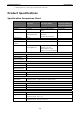
OnCell 5000 Series • Introduction 2 digital inputs and 1 relay output (OnCell 5104 series only) Product Specifications Specification Comparison Chart OnCell OnCell OnCell 5004/5104 5004/5104-HSDPA 5004/5104-HSDPA-JPS 5004/5104-HSDPA-JPN Cellular Interface Standards GSM/GPRS GSM/GPRS/EDGE/UMTS/ UMTS/HSDPA HSDPA Quad-band Options GPRS Multi-slot Quad-band Tri-band 850/1900/2100 MHz 2100 MHz 850/900/1800/1900 Quad-band MHz 850/900/1800/1900 MHz Class 10 - GPRS Terminal Device Class B -
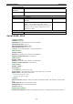
OnCell 5000 Series Introduction Environmental Limits Operating -30 to 55°C (-22 to 131°F), 5 to 95% RH temperature Storage Temperature -40 to 75°C (-40 to 167°F) Regulatory Approvals Safety UL (UL60950) Radio FCC Part 22H, FCC Part 24E, EN301 489-1, EN301 489-7 VCCI - EN301 511 EMC CE: EN55022 Class A / EN55024, FCC: FCC part 15 - subpart B, Class A, EN61000-4-2 (ESD) Level 4, EN61000-4-3 (RS) Level 3, EN61000-4-4 (EFT) Level 4, EN61000-4-5 (Surge) Level 3, EN61000-4-8 Level 3, EN61000-4-12 Le
OnCell 5000 Series Introduction Physical Characteristics Housing: Aluminum, providing IP30 protection Weight: OnCell 5004: 505±5 g OnCell 5104: 645±5 g Dimensions: OnCell 5004: 158 x 103 x 35 mm (6.22 x 4.06 x 1.38 in) OnCell 5104: 135 x 103 x 50.8 mm (5.315 x 4.06 x 2.
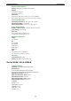
OnCell 5000 Series Introduction Cellular Interface (OnCell 5004/5104-HSDPA-JPS/JPN) Standards: UMTS/HSDPA Band Options: 2100 MHz Tx Power: UMTS/HSDPA: 0.25 W WAN Interface Number of Ports: 1 Ethernet: 10/100 Mbps, RJ45 connector, Auto MDI/MDIX Magnetic Isolation Protection: 1.5 KV built-in LAN Interface Number of Ports: 4 Ethernet: 10/100 Mbps, RJ45 connector, auto MDI/MDIX Magnetic Isolation Protection: 1.
OnCell 5000 Series Introduction Regulatory Approvals (OnCell 5004/5104-HSDPA) Safety: UL: UL60950 RF: FCC Part22H FCC PART24E EN301 489-1 EN301 489-7 EN301 511 EMC: CE: EN55022 Class A / EN55024 FCC: FCC part 15 subpart B, Class A Regulatory Approvals (OnCell 5004/5104-HSDPA-JPS/JPN) EMC: VCCI Warranty Warranty Period: 5 years Details: See www.moxa.
2 2. Getting Started This chapter covers the hardware installation of the OnCell 5000. Software installation is covered in the next chapter.
OnCell 5000 Series Getting Started Panel Layout OnCell 5004/5004-HSDPA/5004-HSDPA-JPS/ 5004-HSDPA-JPN 2-2
OnCell 5000 Series Getting Started OnCell 5104/5104-HSDPA/5104-HSDPA-JPS/ 5104-HSDPA-JPN Left Side Right Side 2-3
OnCell 5000 Series Getting Started DIN-Rail and Rack Mounting Wall or Cabinet Mounting The OnCell 5004, OnCell 5004-HSDPA, and OnCell 5004-HSDPA-JPS device servers have built-in “ears” for attaching the device server to a wall or the inside of a cabinet. We suggest using two screws per ear to attach the device servers to a wall or the inside of a cabinet. The heads of the screws should be less than 6.0 mm in diameter, and the shafts should be less than 3.
OnCell 5000 Series Getting Started SIM Card Installation In order to protect the SIM card, the SIM card slot is located inside the OnCell 5004 and 5104 series’ housing. You will need to unscrew and remove the outer SIM card cover before installing or removing the SIM card.
OnCell 5000 Series Getting Started LED Indicators The following table explains the LED indicators on the front panel of the OnCell 5004-HSDPA/5104-HSDPA: Type PWR 1 PWR 2 2G 3G REG SIM1/2 Color LED Function Green Activation of DC Power Off Power is off, or power error condition exists. Green Activation of DC Power Off Power is off, or power error condition exists.
3 3. Initial IP Address Configuration When setting up the OnCell 5000 for the first time, the first thing you should do is configure the IP address. This chapter introduces the different methods that can be used to do this.
OnCell 5000 Series Initial IP Address Configuration Static and Dynamic IP Addresses Determine whether your OnCell 5000 needs to use a static IP address or dynamic IP address (either DHCP or BOOTP application). • If your OnCell 5000 is used in a static IP environment, you must assign a specific IP address using one of the tools described in this chapter. • If your OnCell 5000 is used in a dynamic IP environment, the IP address will be assigned automatically from over the network.
OnCell 5000 Series Initial IP Address Configuration 1. From the Windows desktop, select Start Æ Run, and then type the following content in the Run window: telnet 192.168.127.254. If your IP address is different from the default setting, use your IP address instead. Click OK. 2. The console terminal type selection is displayed, as shown below. Enter 1 for ansi/vt100, and then press ENTER to continue. 3. The following window will only appear if the OnCell 5000 is password protected.
OnCell 5000 Series Initial IP Address Configuration 4. Press N or use the arrow keys to select Network, and then press ENTER. 5. Press L or use the arrow keys to select LAN, and then press ENTER. 6. Use the arrow keys to move the cursor to IP address. Use the DELETE, BACKSPACE, or SPACE keys to erase the current IP address, and then type in the new IP address and press ENTER. Note that if you are using a dynamic IP configuration (BOOTP, DHCP, etc.
OnCell 5000 Series Initial IP Address Configuration 8. Press A or use the arrow keys to select Save and then press ENTER. Press ENTER again to confirm the save command. 9. Press R or use the arrow keys to select Restart and then press ENTER. Press ENTER again to restart the OnCell 5000. Serial Console The OnCell 5000 can be configured through the serial console, which works the same as the Telnet console but is accessed through the RS-232 console port rather than over the network.
OnCell 5000 Series Initial IP Address Configuration 4. The Property window opens automatically. Select the Communication Parameter tab, and then select the appropriate COM port for the connection (COM1 in this example). Configure the parameters to 115200 for Baud Rate, 8 for Data Bits, None for Parity, and 1 for Stop Bits. 5. From the Property window’s Terminal page, select ANSI or VT100 for Terminal Type and then click OK.
OnCell 5000 Series Initial IP Address Configuration 6. If the OnCell 5000 has been set up for password protection, you will be prompted to enter the password. After you enter the password, or if password protection was not enabled, you will be prompted to select the terminal mode. Press 1 for ansi/vt100 and then press ENTER. 7. The main menu should appear. Once you are in the console, you may configure the IP address through the Network menu, just as with the Telnet console.
4 4. Web Console Configuration In this chapter, we explain all aspects of the web-based console configuration utility. Moxa’s easy-to-use management functions will help you set up your OnCell 5000 and allow you to maintain your wireless network easily.
OnCell 5000 Series Web Console Configuration Accessing the Web Console Open your web browser and enter 192.168.127.254 in the website address line. This is the default IP address for the OnCell 5000—if a new address has been assigned, enter the new address instead. Press ENTER to load the page. ATTENTION The examples and figures in this chapter use the OnCell 5000 factory default IP address of 192.168.127.254.
OnCell 5000 Series Web Console Configuration You must click on the Submit button to keep your configuration changes. The Submit button is located at the bottom of every page that has configurable settings. If you navigate to another page without clicking the Submit button, your settings will be lost. Changes will not take effect until they are saved and the OnCell is restarted! You may complete this in one step by clicking on the Save/Restart option after you submit a change.
OnCell 5000 Series Web Console Configuration Time server: The OnCell 5000 uses SNTP (RFC-1769) for auto time calibration. You may enter a time server IP address or domain name in this optional field. Once the OnCell 5000 is configured with the correct time server address, it will request time information from the time server every 10 minutes. Network Settings LAN Settings You can access LAN Settings by expanding the Network Settings item in the navigation panel.
OnCell 5000 Series Web Console Configuration LAN Port Configuration LAN Port Configuration settings are included to give the user control over Port Access, Port Transmission Speed, Flow Control, and Port Type (MDI or MDIX). An explanation of each configuration item is given below. Enable (default=Yes): Option Description Yes Allows data transmission through the port. No Immediately shuts off port access. Speed (default=Auto): Option Description Auto Allows the port to use the IEEE 802.
OnCell 5000 Series Web Console Configuration Note: You need to select one of the two WAN preferences. If the line is disconnected, the router will not automatically switch to the other WAN preference. NAT service (default=Enable): If you Enable NAT service, LAN-side applications will be able to link to WAN-side applications. Used SIM: Select the SIM card number that has been used, and please ensure inserting SIM card into right slot.
OnCell 5000 Series Web Console Configuration Background 1. “Register to network” and “Establish PPP with ISP” are two steps for establishing connection with the ISP. 2. If GuaranLink determines that the OnCell cannot establish connection with the ISP, it reboots the OnCell in order to allow the OnCell to retry the connection once rebooted. Common Settings • GuaranLink (default=Disable): Enable this setting to start the GuaranLink function.
OnCell 5000 Series Web Console Configuration Ethernet WAN Settings You can access Network Settings Æ Ethernet WAN Settings by expanding the item in the navigation panel. Ethernet WAN Settings is where you assign the OnCell 5000’s IP address, netmask, Gateway, and other parameters for the Ethernet interface. Note: You must assign a valid WAN IP address to your OnCell 5000 before it will work in your network environment.
OnCell 5000 Series Option Auto Web Console Configuration Description Allows the port to use the IEEE 802.3u protocol to negotiate with connected devices. The port and connected devices will determine the best speed for that connection. 10Mbps Half Choose one of these fixed speed options if the opposing Ethernet device has 10Mbps Full trouble auto-negotiating for line speed.
OnCell 5000 Series Web Console Configuration DHCP Settings DHCP (default=Enable): DHCP stands for Dynamic Host Control Protocol. When you enable the DHCP Server, it will automatically assign an IP address to the computers on the LAN/private network. Be sure to set your computers to be DHCP clients by setting their TCP/IP settings to “Obtain an IP Address Automatically.” When you turn your computers on, they will automatically load the proper TCP/IP settings provided by the OnCell 5000.
OnCell 5000 Series Web Console Configuration Report to UDP port (default=63100): This is the UDP port number assignment for the serial port on the OnCell 5000. Report period (default=99): You can use this option to set the automatic report time.
OnCell 5000 Series Web Console Configuration WAN IP Filter The OnCell 5000 uses an IP address-based filtering method to control access to its Ethernet ports. The WAN IP Filter allows you to restrict network access to the OnCell 5000. Access is controlled by IP address. When the WAN IP Filter list is enabled, a WAN’s IP address must be listed in order to gain access to the OnCell 5000.
OnCell 5000 Series Web Console Configuration Route Table You can access the Route Table by expanding Advanced Network Settings in the navigation panel. Use the route table to configure how the OnCell 5000 will connect to an outside network. You are allowed up to 16 entries in the route table. For each entry, you must provide the gateway, destination, netmask type, netmask, metric hops, and interface. Gateway: This is the IP address of the next-hop router.
5 5. System Management Settings In this chapter, we describe the OnCell 5000’s system management settings. The same configuration options are also available through the Telnet and serial console. The following topics are covered in this chapter: Misc.
OnCell 5000 Series System Management Settings Misc. Network Settings SNMP Agent Settings SNMP: To enable the SNMP Agent function, select the Enable option, and enter a community name (e.g., public). Read community string (default=public): This is a text password that is used to weakly authenticate queries to agents of managed network devices. Write community string (default=private): This is a text password that is used to weakly authenticate changes to agents of managed network devices.
OnCell 5000 Series System Management Settings DDNS Configuration DDNS (default=Enable): The Dynamic Domain Name System is a method of keeping a domain name linked to a changing IP Address. Check the box to enable DDNS. Server address: Choose your DDNS provider from the drop down menu. Host name: Enter the Host Name that you registered with your DDNS service provider. Username: Enter the Username for your DDNS account. Password: Enter the Password for your DDNS account.
OnCell 5000 Series NOTE System Management Settings If you select “enable for SMS,” the receiver will receive the message in the following format: [modelName] alert (S/N: [serial number], LAN: [LAN IP], [LAN MAC Address]): (C-WAN/E-WAN/P-WAN: [WAN IP]): (yyyy-mm-dd hh:mm:ss) [message] C-WAN: x.x.x.x E-WAN: x.x.x.x indicates the cellular WAN IP address indicates the Ethernet WAN IP address and “P-WAN: x.x.x.x” indicates the preferred WAN IP address.
OnCell 5000 Series System Management Settings ATTENTION Consult your Network Administrator or ISP for the proper mail server settings. The Auto warning function may not work properly if it is not configured correctly. The OnCell 5000’s SMTP AUTH supports LOGIN, PLAIN, and CRAM-MD5 (RFC 2554). Mail server: This field is for your mail server’s domain name or IP address. User name: This field is for your mail server’s user name, if required.
OnCell 5000 Series System Management Settings Maintenance Console Settings On this screen, access to different OnCell 5000 configuration console options (HTTP, HTTPS, Telnet, SSH) can be enabled or disabled. Refer to Change Password later in this chapter for more information on passwords. Reset button (default=Always Enable): Select “Always Enable” to activate the reset button. Use the “Disable after 60 sec” option to avoid resetting the server when the reset button is pressed accidentally.
OnCell 5000 Series Group System System Management Settings Event System Cold Start, System Warm Start, Power 1 DOWN, Power 2 DOWN, Cell. module awake/fail, Cell. module close/over temperature range Network DHCP/BOOTP Get IP/Renew, NTP, Mail Fail, NTP Connect Fail, IP Conflict, Network Config Login Fail, IP Changed, Password Changed, Config Changed, Firmware Upgrade, Link Down, Cell.
OnCell 5000 Series System Management Settings Load Factory Defaults This function will reset all of the OnCell 5000’s settings to the factory default values. All previous settings, including the console password will be lost. If you wish to keep the OnCell 5000 IP address, netmask, and other IP settings, make sure Keep IP settings is checked before loading the factory defaults.
OnCell 5000 Series System Management Settings SSL certificate is used to ensure that the website you are accessing is the one you trust, and to encrypt the data transmitted between you and the website. The SSL certificate contains unique, authenticated information about the certificate owner. It is issued by a Certificate Authority (CA), such as VeriSign, that verifies the identity of the certificate owner. The OnCell 5000 will generate a new SSL certificate whenever a new IP is used.
OnCell 5000 Series System Management Settings Routing Go to System Monitoring under Routing to display the routing information. Possible flags include: • U: route is up • D: route is down • G: use gateway • +: default gateway • T: static route • H: target is a host DHCP Client List The DHCP Client List shows all the clients that require and have successfully received IP assignments. You can click the Refresh button to refresh the list.
OnCell 5000 Series System Management Settings System Log This option displays the system log. You may click Select all to select the entire log if you wish to copy and paste the contents into a text file. Dout State Dout State refers to the relay output status, which can be configured to change upon the occurrence of certain system events through Auto Warning Settings under System Management. Click Dout State under System Monitoring to display a list of events that may cause a change to the Dout state.
OnCell 5000 Series System Management Settings Save Configuration Go to Save Configuration and then click Save to save your submitted configuration changes to the OnCell 5000’s flash memory. The configuration changes will be effective when the OnCell 5000 is restarted. If you do not save your changes before restarting, they will be discarded. Restart Restart System Go to Restart System under Restart and then click Restart to restart the OnCell 5000.
6 6. Introduction and Configuring VPN In this chapter, we explain how to configure a VPN with the OnCell 5000 web console.
OnCell 5000 Series Introduction and Configuring VPN What Are VPNs? Computers that are part of a VPN use a second, “virtual” IP address to connect to the Internet. Instead of running across a single private network, some of the links between nodes that are part of a VPN use open network connections or virtual circuits on a larger network, such as the Internet. With the help of VPNs, cellular devices acting as a VPN client can initiate a connection with a VPN server.
OnCell 5000 Series Introduction and Configuring VPN OnCell VPN Web Console Settings From the left navigation panel, click Network Advanced Network Settings Æ VPN to configure the OnCell VPN Settings. The configuration items are shown below: Manual Key/ESP Configuration VPN tunnel (default = Disable) : Enable or disable the VPN tunnel function. VPN tunnel mode: The type of VPN tunnel policy to be used; either manual key IPsec or ISAKMP with Pre-shared Keys (PSK).
OnCell 5000 Series Introduction and Configuring VPN Incoming Security Settings SPI: This sets the VPN manual key incoming SPI between 257 and 4294967295. Encryption mode: Select the incoming encryption mode. Encryption key: Enter the incoming encryption key. Encryption mode Length (Bytes) DES 8 3DES 24 AES 128bit 16 AES 192bit 24 AES 256bit 32 Authentication mode: Select the incoming authentication mode. Authentication key: Enter the incoming authentication key.
OnCell 5000 Series Introduction and Configuring VPN ISAKMP/PSK Configuration VPN tunnel (default = Disable) : Enable or disable the VPN tunnel function. VPN tunnel mode: The type of VPN tunnel policy to be used; either manual key IPsec or ISAKMP with Pre-shared Keys (PSK). Remote Network Remote endpoint IP or hostname: Enter the WAN IP or hostname of the remote VPN server endpoint. Remote subnet IP: Enter the remote VPN server subnet IP of the remote network.
OnCell 5000 Series Introduction and Configuring VPN ISAKMP (Key Management) Pre-shared key (PSK): This sets the VPN ISAKMP Pre-Shared key settings. Perfect forward secrecy (PFS) (default = Disable): Enable or disable the Perfect Forward Secrecy. PFS is an additional security protocol. Local Identity Identity option: Select additional ID authentication requirements for the VPN using a specific IP Address, FQDN, or User FQDN settings.
OnCell 5000 Series Introduction and Configuring VPN VPN system log events and error codes VPN system log Description VPN init. VPN tunnel initial VPN init.
7 7. Configuring OnCell Central Management Software In this chapter, we introduce OnCell Central Management Software, and explain how to configure OnCell Central Management Software with the OnCell 5000 web console, install and set the OnCell Central Driver Manager, and cover all of the equipment specifications.
OnCell 5000 Series Configuring OnCell Central Management Software Step 1 Step 2 OnCell Central Manager Ethernet Device OnCell Central Server Step 3 OnCell Device Host Devices Ethernet Step 1: Server Settings System Requirements Hardware Requirements Your computer’s hardware must meets the following minimum requirements: • Pentium III or above • 500 MHz CPU (1 GHz recommended) • 256 Mb RAM (1 GB recommended) • 300 MB disk space Software Requirements OnCell Central Manager runs on the follow
OnCell 5000 Series Configuring OnCell Central Management Software 2. Click Next when the Welcome screen opens to proceed with the installation. 3. Click Next to install program files to the default directory, or click Browse to select an alternate location. 4. Click Next to install the program’s shortcuts in the appropriate Start Menu folder.
OnCell 5000 Series Configuring OnCell Central Management Software 5. Click Next to proceed with the installation. You will be prompted to select additional tasks. 6. Click Next to proceed with installation. Setup will display a summary of the installation options. 7. Click Install to begin installation. The setup window will report the installation progress. To change the installation settings, click Back and navigate to the previous screen.
OnCell 5000 Series Configuring OnCell Central Management Software 8. Click Finish to complete the installation of the OnCell Central Manager. Using OnCell Central Manager After you install OnCell Central Manager, you can set up the OnCell 5000’s OnCell Central Settings for your PC host. Make sure the settings on your OnCell 5000 match the settings for OnCell Central Manager. 1. Go to Start Æ OnCell Central Æ OnCell Central to start the OnCell Central mapping software.
OnCell 5000 Series Configuring OnCell Central Management Software 2. Click on Tool Æ Control Ports Settings to modify the port number. To modify the new configuration of control ports, you can make all configuration changes here. The Control Ports Setting’s information must match the web console’s OnCell Central Server Settings. Please refer to Step 2, OnCell Device Web Console Settings, for control port information. Click Save if any modifications have been made. 3.
OnCell 5000 Series Configuring OnCell Central Management Software 4. If you need to import/add a long pre-defined device list to the OnCell Central Server, follow the next step, otherwise skip directly to Step 9. 5. To import the configuration from a text file, click on Tool Æ Import OnCell User Ports/Service Forwarding. Browse to locate the configuration file (file format can be .txt for the following import format) and then click Import (same step as Import Service Forwarding).
OnCell 5000 Series Configuring OnCell Central Management Software 6. Alternatively, for OnCell User Ports and Service Forwarding, you can manually enter the information. Click on Tool Æ Add OnCell User Ports/Service Forwarding. (Same step as Import Service Forwarding.) 7. In order to view the information you have been imported or added, click on View (same step as Import Service Forwarding).
OnCell 5000 Series Configuring OnCell Central Management Software 8. To save All the configuration settings to an xml file format, select Export DataBase from the OnCell Central menu. You will then be able to import this configuration file to another host and use the same OnCell Central settings on the other host. 9. When all the configurations have been completed, return to the OnCell central main page.
OnCell 5000 Series Configuring OnCell Central Management Software Step 2: OnCell Device Web Console Settings OnCell Central Settings From the left navigation panel, click Network Settings Æ OnCell Central Settings Æ OnCell Central Server to configure the OnCell Central Settings.
OnCell 5000 Series Configuring OnCell Central Management Software Service Forwarding From the left navigation panel, click Network Settings Æ OnCell Central Settings Æ Service Forwarding to configure the OnCell Central Settings. The configuration items are shown below: Service forwarding (default=Disable): If enabled, this option will establish the Ethernet device connection of the OnCell device to OnCell Central Server. Up to 8 Ethernet devices can be stored in the Service Forwarding Table.
OnCell 5000 Series Configuring OnCell Central Management Software 2. Select Security Settings, select Internet, and then click Custom Level. 3. Enable Download signed ActiveX controls. 4. Enable Run ActiveX controls and plug-ins.
OnCell 5000 Series Configuring OnCell Central Management Software 5. Enable Script ActiveX controls marked safe for scripting and then click OK. 6. Select Trusted sites under Security and then click on Sites… 7. Enter your IP address for your OnCell Central’s web page, then click Add.
OnCell 5000 Series Configuring OnCell Central Management Software 8. Click on Custom Level… 9. Enable Download signed ActiveX controls 10.
OnCell 5000 Series Configuring OnCell Central Management Software 11. Enable Script ActiveX controls marked safe for scripting and then click OK OnCell Central Web Console 1. Start the web browser. 2. In the Address input box, enter the OnCell Central’s web IP address follow with the 8080 port (e.g., 192.168.127.111:8080). You should see the OnCell Central Manager Welcome page. 3. Enter the default username and password and then click Login. Username: admin Password: admin 4.
OnCell 5000 Series Configuring OnCell Central Management Software Overview The page shows which OnCell Central Manager version number you are using. Control Ports/User Ports Information. Control Ports Information. Control ports are used to establish a connection between an OnCell device and the OnCell Central Server. This section shows all control port information that has already been configured. User Ports info.
OnCell 5000 Series Configuring OnCell Central Management Software Account Settings For all changes to the OnCell Central’s admin and password protection settings, you will first need to enter the old password. To set up a new password or change the existing password, enter your desired password under both New password and Confirm password. Device This section describes ways in which you can monitor all of the device information that appears in the Device List.
OnCell 5000 Series Configuring OnCell Central Management Software All Devices This table describes All Devices that are connected to OnCell Central Server: Item Device MAC Description Each Device has unique MAC ID that you can find on the device label or web/telnet/serial console Device Name Device’s Name WAN IP Device’s WAN IP address LAN IP Device’s LAN IP address OP mode Device’s operation mode (does not apply to the OnCell 5004 and 5104) FW Version Device’s firmware version Last Connected
OnCell 5000 Series Configuring OnCell Central Management Software After creating the group, you can copy the devices under All Devices folder to create a new folder (e.g., South A). Remove Device. To maintain the list, you can remove all offline devices. To activate this function, click the right mouse button and select Remove Device. Note: If a device is removed from the All Devices Folder then the same device will be removed from all other new folders, too.
OnCell 5000 Series Configuring OnCell Central Management Software Service Forwarding The Service Forwarding table displays the host’s established Ethernet connection to the OnCell Central Server, and the corresponding OnCell devices. Item Description Status Shows the status of the user’s service ports. Closed: this mean the port is not connected Registered: this mean the OnCell is connected to OnCell Central Server.
OnCell 5000 Series Configuring OnCell Central Management Software Clear finished and cancelled upgrades: This button clears all firmware upgrades that have been finished and canceled. Cancel selected devices: This button cancels the firmware upgrading process of the selected device(s). Select All: This button makes it easy to select all of your devices for firmware upgrades. Firmware Upgrade: This button will initiate a firmware upgrade for the devices you have selected.
OnCell 5000 Series Configuring OnCell Central Management Software Overview This page shows the OnCell’s device information: User Ports Telnet Enable: If you click on the enable icon, Telnet will permit the the host to connect to the OnCell device. If no connections are made within 30sec, the port will just close.
OnCell 5000 Series Configuring OnCell Central Management Software Note: If the data or command port is occupied, an error message will appear at the bottom of the window. Service Forwarding Item Description Status Show the status of the User Service Port. Closed: Means the port is not connected. Registered: Mean the OnCell is connected to OnCell Central Server. Connected: Means the host side is connected to OnCell Central Server, and is ready to use.
OnCell 5000 Series Configuring OnCell Central Management Software Maintenance Configuration Export To save all tconfigurations to an xml file, select Configuration Export and then click Download. Configuration Import Allows you to import this configuration file to another host and use the same OnCell Central settings in the other host. Restart OnCell Device Click Restart to restart the OnCell 5000 device.
OnCell 5000 Series Configuring OnCell Central Management Software Logout 7-25
8 8.
OnCell 5000 Series OnCell Search Utility Installing the Search Utility 1. Click the INSTALL UTILITY button in the OnCell Installation CD auto-run window to install OnCell Search Utility. Once the program starts running, click Yes to proceed. 2. Click Next when the Welcome screen opens to proceed with the installation. 3. Click Next to install program files to the default directory, or click Browse to select an alternate location. 4. Click Next to select additional tasks.
OnCell 5000 Series OnCell Search Utility 5. Click Next to proceed with the installation. The installer then displays a summary of the installation options. 6. Click Install to begin the installation. The setup window will report the progress of the installation. To change the installation settings, click Back and navigate to the previous screen. 7. Click Finish to complete the installation of OnCell Search Utility.
OnCell 5000 Series OnCell Search Utility 2. When the search is complete, all OnCell 5000 servers that were located will be displayed in the OnCell Search Utility window. 3. Click Locate to cause the selected device to beep. 4. To modify the configuration of the highlighted OnCell 5000, click on the Console icon to open the web console. This will take you to the web console, where you can make all configuration changes.
OnCell 5000 Series OnCell Search Utility 6. To change the configuration of the IP Address Report, click on the Settings icon to open the IP Location Settings. The Local UDP listen Port number should match the web console Auto IP Report Settings’ port number. 7. Click the Go icon to complete the configuration. Refer to Chapter 4, Using the Web Console, for information on how to use the IP Address Report.
A A. Setting Name Default Settings Default Name Web Console Login Username admin Password Keep Network Settings LAN IP address 192.168.127.254 WAN IP address 192.168.126.254 Network 255.255.255.
B B. Dynamic Domain Name Server This appendix explains how to use the OnCell 5000 with DDNS. When the OnCell 5000 receive its IP address from a DHCP (Dynamic Host Configuration Protocol) server, remote servers will be unable to access it using a fixed IP address. With DDNS (Dynamic Domain Name Server), a remote server can access the OnCell G3100 using its domain name instead of its IP address. Overview The following is a summary of the process: 1.
OnCell 5000 Series Dynamic Domain Name Server The above screenshot shows how DHCP can be set up to update the DNS. Currently, the OnCell 5000 supports DNS service as provided by DynDNS. For detailed information on this option, please visit https://www.dyndns.com. Configuration DDNS (default=Disable): Use this field to enable or disable DDNS. Server address (default=DynDns.org): Currently, DynDns.org is the only option available for Server address.
C C. Auto IP Report Protocol OnCell Series provides several ways to configure the Ethernet IP addresses. One of them is DHCP Client. When you set up the OnCell to use DHCP Client to configure Ethernet IP addresses, it will automatically send a DHCP request over the Ethernet to find the DHCP Server. And then the DHCP Server will send an available IP address to the OnCell. The OnCell will use this IP address for a period of time after receiving it.