G2100 Series User’s Manual Fourth Edition, November 2007 www.moxa.com/product Moxa Technologies Co., Ltd. Tel: +886-2-8919-1230 Fax: +886-2-8919-1231 Web: www.moxa.com Moxa Technical Support support@moxa.com Worldwide: support@usa.moxa.
OnCell G2100 Series User’s Manual The software described in this manual is furnished under a license agreement and may be used only in accordance with the terms of that agreement. Copyright Notice Copyright © 2007 Moxa Technologies Co., Ltd. All rights reserved. Reproduction without permission is prohibited. Trademarks Moxa is a registered trademark of The Moxa Group. All other trademarks or registered marks in this manual belong to their respective manufacturers.
Table of Contents Chapter 1 Introduction ..................................................................................................1-1 Overview.................................................................................................................................. 1-2 Package Checklist .................................................................................................................... 1-2 Features..............................................................................
Flow Control............................................................................................................... 4-13 2-wire RS-485 Communication (OnCell G2150I Only) ........................................................ 4-13 Additional Information .......................................................................................................... 4-14 Chapter 5 GSM/CSD Connection..................................................................................5-1 Overview.............
1 Chapter 1 Introduction The OnCell G2100 Series of industrial GSM/GPRS modems provide an easy way to connect your remote RS-232, or RS-422/485 serial devices to GSM and GPRS mobile networks.
OnCell G2100 Series User’s Manual Introduction Overview The OnCell G2100 Series modem is a quad-band GSM/GPRS modem that transmits data and short messages (SMS) over GSM/GPRS mobile networks. The modem can be used to improve the efficiency of your maintenance and communication, and does not require a high level of technical knowledge to operate.
OnCell G2100 Series User’s Manual Introduction y Seperate RS-422/485 interface (OnCell G2150I only) y 2.
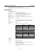
OnCell G2100 Series User’s Manual Introduction Serial Communication Parameters Parity None, Even, Odd, Space, Mark Data Bits 7, 8 Stop Bits 1, 2 Flow Control RTS/CTS, None Transmission Speed 300 bps to 115.2 Kbps RS-422/485 Termination 120Ω, DIP switch controlled (OnCell G2150I only) RS-422/485 Pull 150 KΩ, 1 KΩ (OnCell G2150I only) High/Low Isolation 2.
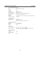
OnCell G2100 Series User’s Manual Introduction Pin Assignments 5 4 3 21 9876 1 DB9 (Female) for RS-232 5 Terminal Block for RS-422/485 RS-485* RS-485* (4-wire) (2-wire) Pin RS-232 RS-422* 1 DCD TxD+ TxD+ --2 TxD TxDTxD--3 RxD RxD+ RxD+ Data + (B) 4 DSR RxDRxDData – (A) 5 GND ------6 DTR ------7 CTS ------8 RTS ------*RS-422 and RS-485 are available on the OnCell G2150I only 1-5
2 Chapter 2 Getting Started This chapter includes instructions on how to install the OnCell G2100 Series modem.
OnCell G2100 Series User’s Manual Getting Started Product Characteristics 1. 12-48V DC Terminal Block 2. H/W RESET Button 3. SMA Antenna Connector 9. DIN/Wall Mount Kit 10. Protected SIM Cover 4. Cellular Signal Level LED 5. PWR/GSM/GPRS/Data LED 11. Antenna 6. Isolated RS-232Port 7. 6-pin DIP Switch 8.
OnCell G2100 Series User’s Manual Getting Started OnCell G2110, G2110-T 89,30 [3,516"] 123,00 [4,843"] 76,00 [2,992"] 27,00 [1,063"] 2-3
OnCell G2100 Series User’s Manual Getting Started Connecting the Hardware This section describes how to connect the OnCell G2100 Series modem to a host PC or serial devices for initial testing and configuration. Wiring Requirements ATTENTION Safety First! Be sure to disconnect the power cord before installing and/or wiring your device. Wiring Caution! Calculate the maximum possible current in each power wire and common wire.
OnCell G2100 Series User’s Manual Getting Started SIM Card Installation In order to protect the SIM card, the SIM card slot is located inside the casing. You will need to unscrew and remove the outer cover before installing or removing the SIM card. PRESS LOCK 2 1 OPEN SIM Cover Follow these steps to remove or install the SIM card: 1. Unscrew the outer cover. 2. Slide the outer cover to the left to remove it. 3. Slide the SIM card cradle to the left and pull it towards you.
OnCell G2100 Series User’s Manual Getting Started STEP 1: Use a flat-blade screw driver to pull the bottom mounting appendage out. It should snap into place. STEP 2: Hook the modem over the top edge of the DIN-rail as shown. STEP 3: STEP 4: Place the modem flush against the DIN-rail as Slide the bottom mounting appendage back in. It shown. should snap into place over the bottom edge of the DIN-rail.
OnCell G2100 Series User’s Manual Getting Started ATTENTION Grounding and wire routing help limit the effects of noise due to electromagnetic interference (EMI). There are two grounding points for the unit. One point is the 3-pin terminal block connector for power. Underneath the bottom mounting appendage is another grounding point. For DIN-rail mounted units: Ground the DIN-rail itself. The modem's grounding point under the mounting appendage will be in direct contact with the rail.
OnCell G2100 Series User’s Manual Getting Started Wall Mounting Follow the intructions below to mount the OnCell Series modem on a wall: STEP 1: Remove the 3-pin power terminal block. For the OnCell G2150I, also remove the 5-pin RS-422/485 terminal block. STEP 2: Use a flat-blade screw driver to pull out both the top and bottom mounting appendages. STEP 3: Use screws and the mounting appendages to mount the unit onto the wall. STEP 4: Reattach the terminal block(s) to the modem.
OnCell G2100 Series User’s Manual Getting Started Connecting the Antenna ATTENTION Make sure the transmitter antenna is placed so that it is at least 20 cm (8 inches) away from any people or users. The modem is not designed for applications where users will be in close proximity for prolonged periods.
OnCell G2100 Series User’s Manual Getting Started A terminal block adaptor with power jack connector is provided to connect to AC power instead of DC power. Compatible AC power adaptors are listed on the Moxa website, www.moxa.com. ATTENTION Always install the antenna first and then connect power. Do not connect power if the antenna has not been installed! Doing so may damage the unit.
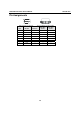
OnCell G2100 Series User’s Manual Getting Started Serial Interface RS-232 RS-422 4W RS-485 2W RS-485 SW1 ON OFF OFF OFF Termination Resistor Enabled Disabled SW4 ON OFF Pull High/Low Resistor 1 KΩ 150 KΩ SW5 ON OFF SW2 OFF OFF ON ON SW3 OFF OFF OFF ON SW6 ON OFF LED Indicators Name SIGNAL (3 LEDS) PWR Color Function Green Signal level (data transmission requires at least 2 bars) Green GSM Amber GPRS DATA Amber Green DC power connection Steady: GSM/CSD connected Blinking: SMS Tunnel is
3 Chapter 3 OnCell Configurator Most modems are configured using AT commands. Moxa's OnCell Configurator provides an easy and convenient alternative to configure the OnCell 2100 Series modem.
OnCell G2100 SeriesI User’s Manual OnCell Configurator Overview OnCell Configurator is a PC-based utility for managing and configuring your OnCell G2100 Series modem. With its Windows-based graphical interface, even first-time users will find it easy to learn. You can configure general settings, modes, and dial-out parameters without any knowledge of the associated AT commands.
OnCell G2100 SeriesI User’s Manual OnCell Configurator Installing OnCell Configurator To install OnCell Configurator, follow the instructions below. After installation, users will be able to use the Configurator, Wizard, and Terminal Emulator for further operations. ATTENTION OnCell Configurator supports Windows 2000, XP, 2003, and Vista. 1. Find the installation file on the Document and Software CD.
OnCell G2100 SeriesI User’s Manual OnCell Configurator 4. Choose I accept the agreement and click Next. 5. Click Next to proceed.
OnCell G2100 SeriesI User’s Manual OnCell Configurator 6. Click Next, or browse to a proper folder to proceed. 7. Click Next to proceed.
OnCell G2100 SeriesI User’s Manual OnCell Configurator 8. Click Next to proceed. 9. Click Install to start the software installation.
OnCell G2100 SeriesI User’s Manual OnCell Configurator 10. Wait until the installation is complete. 11. Click Next to proceed.
OnCell G2100 SeriesI User’s Manual 12. OnCell Configurator Click Finish. Launching OnCell Configurator 1. Start OnCell Configurator from the Windows Start menu.
OnCell G2100 SeriesI User’s Manual OnCell Configurator 2. Select one of the three options: 3. Whether you use the Configurator or the Wizard, any modifications to the settings will not go into effect until you click Apply.
OnCell G2100 SeriesI User’s Manual OnCell Configurator Configuring Serial Connection and Device Name The following instructions explain how to configure the serial communication parameters using Configurator. 1. Connect the RS-232 port of the OnCell G2100 Series modem to a host PC. On the OnCell G2150I, make sure the RS-232 port is connected and DIP switch 1 is set to ON. 2. Start OnCell Configurator and select Create a new Configuration File from Configurator. 3.
OnCell G2100 SeriesI User’s Manual OnCell Configurator ATTENTION Use the command AT+IPR=0 to enable Autobauding. Please refer to Chapter 4 for details. Autobauding and the +++ escape command only work with 8n1 and e71 settings. Using other settings will disable these functions. Stop bits can only be set to 2 only when parity is set to none. The default parameters are 115200, 8n1, and RTS/CTS flow control.
OnCell G2100 SeriesI User’s Manual 3. OnCell Configurator On the Configure the Serial Interface page, click Modify and configure the serial device settings. Enter the device name in the text input box.
OnCell G2100 SeriesI User’s Manual OnCell Configurator Configuring the PIN Setting The following instructions explain how to configure the PIN code using Configurator. 1. Connect the RS-232 port of the OnCell G2100 Series modem to a host PC. On the OnCell G2150I, make sure the RS-232 port is connected and DIP switch 1 is set to ON. 2. Start OnCell Configurator and select the Create a new Configuration File from Configurator option. 3.
OnCell G2100 SeriesI User’s Manual OnCell Configurator ATTENTION Once the correct PIN is entered using the AT+ CPIN command or OnCell Configurator, the system (firmware V1.2 or above) will activate the Automatic PIN Entry function. This function will store the current PIN in its memory, and then enter the PIN automatically each time the system boots up. If the SIM card does not match the current PIN, the Automatic PIN Entry function will be deactivated.
OnCell G2100 SeriesI User’s Manual 3. OnCell Configurator On the PIN and Band Management page, enter the correct PIN in the text input box. Configuring the Radio Band The following instructions illustrate how to configure the radio band using Configurator. 1. Connect the RS-232 port of the OnCell G2100 Series modem to a host PC. On the OnCell G2150I, make sure the RS-232 port is connected and DIP switch 1 is set to ON. 2.
OnCell G2100 SeriesI User’s Manual 3. OnCell Configurator On the GSM Setting tab, select the correct radio band for your application. The following instructions illustrate how to configure the radio band using the Wizard. 1. Connect the RS-232 port of the OnCell G2100 Series modem to a host PC. On the OnCell G2150I, make sure the RS-232 port is connected and DIP switch 1 is set to ON. 2. Start OnCell Configurator and select the Create a new Configuration File from Wizard option.
OnCell G2100 SeriesI User’s Manual 3. OnCell Configurator On the PIN and Band Management page, select the correct radio band for your application. Initial Strings The following instructions illustrate how to configure the initial strings using Configurator. 1. Connect the RS-232 port of the OnCell G2100 Series modem to a host PC. On the OnCell G2150I, make sure the RS-232 port is connected and DIP switch 1 is set to ON. 2.
OnCell G2100 SeriesI User’s Manual 3. OnCell Configurator On the Init. Strings tab, enter the initial string in the text input box. ATTENTION A maximum of 39 characters is allowed for each initial string. Saving the Configuration Profile The following instructions illustrate how to configure the serial communication parameters using Configurator. 1. Connect the RS-232 port of the OnCell G2100 Series modem to a host PC.
OnCell G2100 SeriesI User’s Manual OnCell Configurator 3. Select Save File from the File menu. 4. Select a folder and enter the file name for the profile. Click Save.
OnCell G2100 SeriesI User’s Manual OnCell Configurator Applying Modem Settings The following instructions illustrate how to apply the current settings to an OnCell G2100 Series modem using Configurator. 1. Connect the RS-232 port of the OnCell G2100 Series modem to a host PC. On the OnCell G2150I, make sure the RS-232 port is connected and DIP switch 1 is set to ON. ATTENTION The RS-232 connector uses the standard pinouts.
OnCell G2100 SeriesI User’s Manual OnCell Configurator 3. Click Apply. 4. Select the appropriate COM port and communication parameters for connecting to the modem. Click OK to proceed. ATTENTION If you are not sure which communication parameters you should use, please select the Auto Detect Serial Settings option and follow the onscreen instructions. The procedure may take few minutes to complete.
OnCell G2100 SeriesI User’s Manual 5. OnCell Configurator Wait a few moments for the settings to be applied. Click OK to finish.
OnCell G2100 SeriesI User’s Manual OnCell Configurator Retrieving the Modem Settings The following instructions illustrate how to use Configurator to get the current settings of an OnCell G2100 Series modem. 1. Connect the RS-232 port of the OnCell G2100 Series modem to a host PC. On the OnCell G2150I, make sure the RS-232 port is connected and DIP switch 1 is set to ON. ATTENTION The RS-232 connector uses the standard pinouts.
OnCell G2100 SeriesI User’s Manual OnCell Configurator 3. Click the Get Settings button on the right side of the window. 4. Select the appropriate COM port and communication parameters for connecting to the modem. Click OK to proceed. ATTENTION If you are not sure which communication parameters you should use, please select the Auto Detect Serial Settings option and follow the onscreen instructions. The procedure may take few minutes to complete.
OnCell G2100 SeriesI User’s Manual OnCell Configurator 5. Wait a few moments for the settings to be retrieved. Click OK when prompted. 6. The settings will be displayed in the Configurator window. The current firmware version will also be displayed.
OnCell G2100 SeriesI User’s Manual OnCell Configurator Loading a Profile The following instructions illustrate how to load a profile using Configurator. 1. Connect the RS-232 port of the OnCell G2100 Series modem to a host PC. On the OnCell G2150I, make sure the RS-232 port is connected and DIP switch 1 is set to ON. 2. Start OnCell Configurator and select the Create a new Configuration File from Configurator option. 3. In the File menu, select Load File from….
OnCell G2100 SeriesI User’s Manual OnCell Configurator 4. Select a folder and profile and click Open. 5. The modem configuration stored in the profile will be displayed in Configurator. The following instructions illustrate how to load a profile using the Wizard. 1. Connect the RS-232 port of the OnCell G2100 Series modem to a host PC. On the OnCell G2150I, make sure the RS-232 port is connected and DIP switch 1 is set to ON.
OnCell G2100 SeriesI User’s Manual OnCell Configurator 2. Start OnCell Configurator and select the Load an existing Configuration file to Configurator option. 3. Select a folder and profile and click Open.
OnCell G2100 SeriesI User’s Manual 4. OnCell Configurator The modem configuration stored in the profile will be displayed in Configurator.
OnCell G2100 SeriesI User’s Manual OnCell Configurator Signal Strength Monitor The following instructions illustrate how to configure the serial communication parameters using Configurator. 1. Connect the RS-232 port of the OnCell G2100 Series modem to a host PC. On the OnCell G2150I, make sure the RS-232 port is connected and DIP switch 1 is set to ON. ATTENTION The RS-232 connector uses the standard pinouts.
OnCell G2100 SeriesI User’s Manual OnCell Configurator 3. Click the Sig. Strength button on the right side of the window. 4. Select the appropriate COM port and communication parameters for connecting to the modem and click OK to proceed. ATTENTION If you are not sure which communication parameters you should use, please select the Auto Detect Serial Settings option and follow the onscreen instructions. The procedure may take few minutes to complete.
OnCell G2100 SeriesI User’s Manual 5. OnCell Configurator Wait a few moments for the signal strength and the carrier information to be queried. Click OK to finish.
OnCell G2100 SeriesI User’s Manual OnCell Configurator 2. Start OnCell Configurator and select Create a new Configuration File from Configurator. 3. Click Upgrade FW on the right side of the window. 4. Upgrading the firmware will clear all current configuration settings in the OnCell G2100 Series modem. To exit and save the current settings, click NO. To proceed, click Yes.
OnCell G2100 SeriesI User’s Manual 5. OnCell Configurator Select a firmware file from the disk and click Open to proceed. ATTENTION Be sure to use the right firmware image file for your model. The OnCell G2110 and OnCell G2110-T both use the same firmware image file. The OnCell G2150I uses a different firmware image file. 6. Select the appropriate COM port and communication parameters for connecting to the modem. Click OK to proceed.
OnCell G2100 SeriesI User’s Manual OnCell Configurator ATTENTION If you are not sure which communication parameters you should use, please select the Auto Detect Serial Settings option and follow the onscreen instructions. The procedure may take few minutes to complete. When using the Auto Detect Serial Settings function, if the GSM or the GPRS LED is ON or blinking, you must remove the SIM card, or use the escape command (+++) on the terminal to disconnect the current connection.
OnCell G2100 SeriesI User’s Manual OnCell Configurator Setting Modem Defaults The following instructions illustrate how to use Configurator to load the factory default settings into the OnCell G2100 Series modem. 1. Connect the RS-232 port of the OnCell G2100 Series modem to a host PC. On the OnCell G2150I, make sure the RS-232 port is connected and DIP switch 1 is set to ON. ATTENTION The RS-232 connector uses the standard pinouts.
OnCell G2100 SeriesI User’s Manual OnCell Configurator 3. Click Set Defaults on the right side of the window. 4. Select the appropriate COM port and communication parameters for connecting to the modem and click OK to proceed. ATTENTION If you are not sure which communication parameters you should use, please select the Auto Detect Serial Settings option and follow the onscreen instructions. The procedure may take few minutes to complete.
OnCell G2100 SeriesI User’s Manual 5. OnCell Configurator Wait a few seconds for the default settings to load and click OK to finish. On recent hardware revisions of the OnCell G2100 Series modem, default settings can be restored using the reset button. Simply hold the RESET button down for 10 seconds and the modem will be reset to the factory default settings. This feature is implemented on the following model revisions and later: the OnCell G2150I Rev. 1.3, OnCell G2110 Rev 1.1, and OnCell G2110-T Rev.
4 Chapter 4 AT Command Set The AT Command Set can be used to operate, configure and query the OnCell G2100 Series modem. This chapter includes information about the AT Command Set of the OnCell G2100 Series modem.
OnCell G2100 Series User’s Manual AT Command Set AT Command Set Introduction The OnCell G2100 Series modem supports the V.25ter AT command set. The "AT" prefix (also known as the Attention Code) signals the modem that one or more commands are to follow. The AT command set is an industry-standard language that is used to communicate with modems. The OnCell G2100 Series modem is always either in command mode or in on-line mode. When first powered up, the modem will enter command mode.
OnCell G2100 Series User’s Manual AT Command Set Starting Moxa Terminal Emulator The following instructions explain how to install the Moxa PComm Lite Package. After installing PComm Lite, you can use the built-in Moxa Terminal Emulator to handle your modem operations. ATTENTION OnCell Terminal Emulator is designed for Windows 2000, XP, 2003, and Vista. If you are running Windows 98, ME, or NT, use PComm Lite V2.6, which can be downloaded on the Moxa website. 1.
OnCell G2100 Series User’s Manual AT Command Set 4. Select the target COM port and communication parameters. Click OK to open the port. 5. Terminal Emulator will connect to the target COM port.
OnCell G2100 Series User’s Manual AT Command Set AT Command Examples The following examples can give users a better understanding of how to use the AT Commands. ATTENTION Make sure that the RS-232 port of the OnCell G2100 Series modem is connected. For the OnCell G2150I, make sure DIP switch 1 is set to ON. Modem Acknowledgement Connect the RS-232 port of the OnCell G2100 Series modem to a host PC.
OnCell G2100 Series User’s Manual AT Command Set Signal Strength Verification 0 to 12 Weak or insufficient 13 to 19 Average 20 to 31 Exceptional 99 No signal BER ranges from 0 to 7, with 7 corresponding to a higher error rate. ATTENTION RSSI should be higher than 12 if you wish to create or accept GSM/CSD data calls or establish a GPRS connection. If the RSSI is less than 12, you will only be able to transmit and receive SMS (short message).
OnCell G2100 Series User’s Manual AT Command Set For example, users in North America would type the following: PIN Code Management Operation of the OnCell G2100 Series modem requires the installation of an active SIM (Subscriber Identity Module) card. The SIM card contains the necessary data to identify the modem to the network service provider. It is also used to store the GSM/GPRS modem PIN (Personal Identification Number.) and PUK (Personal Unblocking Key), which are also used with mobile phones.
OnCell G2100 Series User’s Manual AT Command Set 3. If the modem responds with +CPIN: SIM PIN, type AT+CPIN= where is the correct PIN. Press Enter. The following example shows "0000" being entered for the PIN. ATTENTION Be careful when entering the PIN codes. After 3 unsuccessful attempts at entering the PIN, you will need to use the PUK to proceed. PUK validation forces the user to enter a new PIN code as a second parameter, and this will be the new PIN code if PUK validation succeeds.
OnCell G2100 Series User’s Manual AT Command Set 3. To enable the facility lock, type AT+CLCK=“SC”,1, The following example shows "0000" being used for the PIN. ATTENTION Once the correct PIN is entered, the system (firmware V1.2 or above) will activate the Automatic PIN Entry function. This function will store the current PIN in its memory and enter it into the OnCell G2100 Series modem each time the system boots up.
OnCell G2100 Series User’s Manual AT Command Set Serial Line Settings ATTENTION Changes to the serial communication parameters take effect immediately. You will need to update your terminal settings to match any changes in the serial communication parameters. Configuration can also be performed with the AT*SERIAL command or OnCell Configurator. The default serial communication parameters are 115200 bps, 8 data bits, None parity, RTS/CTS flow control, and 1 stop bit.
OnCell G2100 Series User’s Manual AT Command Set 3. Type AT&W and press Enter to save the settings. Modifying Data Bits and Parity 1. Type AT+ICF=x,y and press Enter, where x and y correspond to the following parameters.
OnCell G2100 Series User’s Manual AT Command Set 2. Modify the terminal settings to match the new serial communication parameters. 3. Type AT&W and press Enter to save the settings. ATTENTION Changes to the serial communication parameters take effect immediately. You will need to update your terminal settings to match any changes in the serial communication parameters. Autobauding and +++ escape command only work with 8n1 or e71 settings. Using other settings will disable these functions.
OnCell G2100 Series User’s Manual AT Command Set Flow Control The default RTS/CTS flow control setting is none. Follow these steps to enable flow control: 1. Type AT+ICF=2,2 and press Enter. To disable flow control again, type AT+ICF=0,0 and press Enter. 2. Type AT&W and press Enter to save the settings. ATTENTION Changes to the serial communication parameters take effect immediately. You will need to update your terminal settings to match any changes in the serial communication parameters.
OnCell G2100 Series User’s Manual AT Command Set 4. Type AT&W and press Enter to save the settings. Note that because the local echo is disabled, users will no see any response from the modem at the terminal screen. AT&W is entered here. OK is the response from the modem. 5. On the bottom of the modem, set DIP switch 1 to OFF, DIP switch 2 to ON, and DIP switch 3 to ON. This configures the modem for 2-wire RS-485 communication. Additional Information z z z z z V.
5 Chapter 5 GSM/CSD Connection A Circuit-Switched Data Connection makes the wireless modem work in a manner similar to a regular analog modem. You must have CSD service in order to make a CSD call.
OnCell G2100 Series User’s Manual GSM/CSD Connection Overview CSD (Circuit Switched Data) is the original form of data transmission developed for GSM systems. By using a single radio time slot, CSD is able to deliver 9.6 to 14.4 kbit/s data transmission to both the GSM network and PSTN switching subsystem through direct calls. Most of the time, it is initiated by standard AT commands. Using the modem to access remote devices by CSD is often more convenient than installing cables and data lines.
OnCell G2100 Series User’s Manual GSM/CSD Connection 2. Type ATD and press Enter. For example, type ATD 0289191230 if the phone number is 0289191230. 3. Check the GSM indicator on the front panel of the modem. If the LED is on and an amber color, the CSD connection has been established successfully. You can switch to data mode to proceed with data communication. 4. To close the CSD connection, type +++.
OnCell G2100 Series User’s Manual GSM/CSD Connection Answering a CSD Connection PComm Terminal Emulator can be used to answer a CSD call manually: 1. When the terminal displays "RING", type ATA and press Enter. 2. Check the GSM indicator on the front panel. If the LED is on and an amber color, the CSD connection has been established successfully. The modem will automatically switch to data mode. At this point, you can proceed with data communication.
OnCell G2100 Series User’s Manual GSM/CSD Connection ATTENTION ATA is the answer command. ATS0= is the auto-answer command. The AT&W command saves the current settings to the modem. It is much easier to configure auto-answer with OnCell Configurator. On the GSM Setting tab, select Enable Auto-answer on ___ Rings and enter the desired number of rings. ATTENTION If you are answering a call from a PSTN dial-up modem, type AT+CICB=0 to force the incoming call to be a data call.
6 Chapter 6 Using Short Message Services GSM technology offers the benefit of using SMS (short message service) as an easy way to communicate over the mobile network. In this chapter, we explain how to use SMS with the OnCell G2100 Series modem.
OnCell G2100 Series User’s Manual Using Short Message Services Sending Short Messages Follow these instructions to send a short message to a specific phone number. 1. Type AT+CMGF=1 and press Enter. 2. Type AT+CMGS="" and press Enter. The terminal will present a ">" prompt. Enter your message at the prompt. 3. Press Ctrl + Z to deliver the message. Press Ctrl+Z here ATTENTION AT+CMGF=1 sets the SMS to Text mode.
OnCell G2100 Series User’s Manual Using Short Message Services In the example, the storage number is 5, which means that the message is stored in the 5th storage location. Deleting Short Messages Follow these instructions to delete a short message. 1. Type AT+CMGD=x,n and press Enter.
OnCell G2100 Series User’s Manual Using Short Message Services SMS Tunnel Mode A major benefit of GSM technology is that it supports short messages (SMS) for easy communication over the mobile network. Moxa’s proprietary SMS Tunnel Mode allows you to expand your applications and reduce cost. For example, SMS Tunnel Mode can be used to update the message on a highway display panel, place refill orders for vending machines, or handle maintenance for remote rental equipment.
OnCell G2100 Series User’s Manual Using Short Message Services 3. On the SMS Tunnel tab, select SMS-IN to forward incoming short messages to the attached serial device. Select SMS-OUT to transmit serial data from the attached serial device as SMS messages. The Caller ID Verification (phone number) and Target Phone Number should be specified.
OnCell G2100 Series User’s Manual Using Short Message Services ATTENTION The Target Phone Number must be specified if SMS-OUT is activated. The Target Phone Number and Caller ID Verification must be written in international format, starting with “+” followed by the country code. If you leave Caller ID Verification blank, the OnCell G2100 Series modem will allow all incoming short messages to be forwarded to the attached serial device. This includes system broadcasts and advertisements.
OnCell G2100 Series User’s Manual 3. Using Short Message Services Select SMS Tunnel Mode and click Next to proceed. ATTENTION Transparent Mode provides the general functions of a GSM/GPRS modem. 4. On the SMS Tunnel Mode Settings page, select SMS-IN to forward incoming short messages to the attached serial device. Select SMS-OUT to transmit serial data from the attached serial device as SMS messages. The Caller ID Verification (phone number) and Target Phone Number should be specified.
OnCell G2100 Series User’s Manual Using Short Message Services SMS Data Format Text ASCII Binary Unicode 7 bits text format (160 bytes per packet) 8 bits binary (140 bytes per packet) 16 bits Unicode (UCS2) format (70 bytes per packet) ATTENTION The Target Phone Number must be specified if SMS-OUT is activated. The Target Phone Number and Caller ID Verification must be written in international format, starting with “+” followed by the country code.
7 Chapter 7 The following topics are covered in this chapter: GPRS Overview Windows GPRS Access ¾ Installing Modem Driver ¾ Modem Diagnostics ¾ Setting up the APN ¾ Adding Windows DUN Entr GPRS Connection
OnCell G2100 Series User’s Manual GPRS Connection GPRS Overview GPRS is a packet-switched technology, which means that multiple users share the same transmission channel. In addition, transmission only occurs when there is outgoing data. This means that the available bandwidth can be dedicated solely to data communication as needed. In general, a GPRS network can be viewed as a special IP network that offers IP connectivity to IP terminals.
OnCell G2100 Series User’s Manual GPRS Connection Installing Modem Driver 1. In the Control Panel, open “Phone and Modem Options” and go to the “Modem” tab. Click Add to add a new modem. ATTENTION The first time you access the Phone and Modem Options, Windows will ask you to input the area code. Enter the area code to proceed. 2. When the Install Mode window opens, select Don’t detect my modem, I will select it from a list and click Next.
OnCell G2100 Series User’s Manual GPRS Connection 3. Next, click Have Disk. 4. When the Install From Disk window opens, click Browse. 5. Select the OnCell_G2100_Series.inf driver. The file is located in the Win_Driver directory on the Document and Software CD. Click Open to proceed.
OnCell G2100 Series User’s Manual GPRS Connection 6. When the Install From Disk page opens, click OK. 7. Click Next.
OnCell G2100 Series User’s Manual GPRS Connection 8. When the next window opens, select the COM port that you are using and click Next. 9. A message will appear stating that the driver has not passed Windows Logo testing. Click Continue Anyway to proceed.
OnCell G2100 Series User’s Manual GPRS Connection 10. Click Finish to complete the installation procedure. 11. At this point, the OnCell G2100 Series driver should be listed in “Phone and Modem Options” on the “Modems” tab.
OnCell G2100 Series User’s Manual GPRS Connection Modem Diagnostics The following instructions explain how to verify that the modem is installed properly and has been activated. 1. From the Control Panel, open Phone and Modem Options. On the Modem tab, click Properties. ATTENTION Make sure that the RS-232 port of the OnCell G2100 Series modem is connected. For the OnCell G2150I, make sure DIP switch 1 is set to ON. Make sure the SMS Tunnel Mode is disabled.
OnCell G2100 Series User’s Manual GPRS Connection 2. On the Diagnostics tab, click Query Modem. 3. If the query is successful, you will be able to see commands that are sent to the modem and the modem's responses.
OnCell G2100 Series User’s Manual GPRS Connection Setting up the APN Before using GPRS connection in Windows, the APN (Access Point Name) must be added as a modem initialization command. The following instructions explain how to set up the APN. ATTENTION Check the signal strength indicators on the front panel of the OnCell G2100 Series modem. If the LED indicators are dark, then the SIM card is not installed properly, or the modem is not picking up a signal.
OnCell G2100 Series User’s Manual GPRS Connection 2. On the Advanced tab, enter the following in the Extra initialization commands field: AT+CGDCONT=1,"IP","" For , use the correct service for your account, as in this example; AT+CGDCONT=1,"IP","ISP.CINGULAR ATTENTION The APN should be entered between the displayed brackets. Remember that the APN is case sensitive. Note that "IP" should be written in all capital letters.
OnCell G2100 Series User’s Manual GPRS Connection Adding Windows DUN Entry The following instructions explain how to add a Windows Dial-up Networking entry. 1. In the Control Panel, open Network Connections and click Create a new connection. 2. When the New Connection Wizard window opens, select Connect to the Internet and click Next. 3. Select Set up my connection manually and click Next.
OnCell G2100 Series User’s Manual GPRS Connection 4. Select Connect using a dial-up modem and click Next. 5. Enter the name of your service provider and click Next.
OnCell G2100 Series User’s Manual GPRS Connection 6. Enter *99***1# for the phone number and click Next. ATTENTION The phone number *99***1# is a special phone number that is used globally to request GPRS IP service from the carrier. DO NOT modify this phone number in any way. The same number is used regardless of the country that you are located in. 7. Enter the User name and Password as prompted and click Next.
OnCell G2100 Series User’s Manual GPRS Connection ATTENTION For a list of User names and Passwords, refer to APN List on the Document and Software CD, or consult your service provider for further details. 8. Click Finish. 9. In the next window that opens, click Properties.
OnCell G2100 Series User’s Manual GPRS Connection 10. Verify that Use dialing rules on the General tab is NOT selected. 11. On the Networking tab, select Internet Protocol (TCP/IP) and click Properties to set the DNS IP address.
OnCell G2100 Series User’s Manual GPRS Connection 12. If you know the IP address of the DNS server, select Use the following DNS server addresses and enter the IP address(es) as prompted. Click OK. ATTENTION For detailed DNS information, please refer to the APN List on the Document and Software, or consult your service provider for further details.
OnCell G2100 Series User’s Manual GPRS Connection 13. Click OK. 14. In the next window that appears, click Dial to establish the connection.
A Appendix A GPRS with UC-7110, UC-7112 Moxa’s UC-7110 and UC-7112 are small embedded computers that can be used for applications such as transportation control, light control, factory/building automation, and power utilities. However, for some applications it is either inconvenient or impossible to connect to the embedded computers with a traditional landline. In this case, the OnCell G2100 Series modem is a great solution for providing GSM/GPRS connectivity to the UC-7110 or UC-7112.
B Appendix B Federal Communication Commission Interference Statement This equipment has been tested and found to comply with the limits for a Class A digital device, pursuant to Part 15 of the FCC Rules. These limits are designed to provide reasonable protection against harmful interference in a residential installation.