
User`s manual
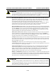
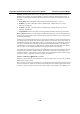
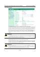
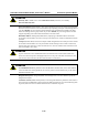
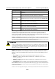
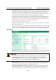
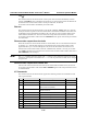
Table Of Contents
- 1. Introduction
- 2. Getting Started
- 3. Initial IP Address Configuration
- 4. Introducing Serial Port Operation Modes
- 5. Introducing OnCell Central and Ethernet Operation Modes
- 6. Using the Web Console
- 7. Cellular Network Settings
- 8. Configuring Serial Port Operation Modes
- 9. Configuring the Cellular-Enabling Ethernet Device
- 10. Configuring OnCell Central Management Software
- 11. Additional Serial Port Settings
- 12. System Management Settings
- 13. Software Installation/Configuration
- A. Pinouts and Cable Wiring
- B. RFC2217
- C. Dynamic Domain Name Server
- D. Well Known Port Numbers
- E. Auto IP Report Protocol
- F. GSM Alphabet
- G. Default Settings
OnCell G3111/G3151/G3211/G3251 Series User’s Manual Serial Port Operation Modes
8-16
the internal buffer. The OnCell G3111/G3151/G3211/G3251 transmits data stored in the buffer via
TCP/IP, but only when the internal buffer is full or as specified by the force transmit time. When set
to 0, the force transmit time is disabled, and transmission is determined solely by the data in the
internal buffer. At 1 to 65535, the TCP/IP protocol software will pack the serial data received after
there is a gap in serial communication that exceeds the specified force transmit time.
The optimal force transmit time depends on your application, but it must be at least larger than one
character interval within the specified baudrate. For example, assume that the serial port is set to
1200 bps, 8 data bits, 1 stop bit, and no parity. In this case, the total number of bits needed to send a
character is 10 bits, and the time required to transfer one character is
(10 (bits) / 1200 (bits/s)) × 1000 (ms/s) = 8.3 ms.
Therefore, you should set the force transmit time to be larger than 8.3 ms, so in this case, it must be
greater than or equal to 10 ms.
If it is necessary to send a series of characters in the same packet, the serial device will need to send
that series of characters within the specified force transmit time, and the total length of data must be
less than or equal to the OnCell G3111/G3151/G3211/G3251’s internal buffer size (1 KB per port).
UDP Mode
Destination address 1 through 4 (default=None): In UDP mode, you may specify up to 4 ranges of
IP addresses for the serial port to connect to. At least one destination range must be provided.
ATTENTION
The maximum selectable IP address range is 64 addresses. However, when using multicast, you
may enter IP addresses of the form xxx.xxx.xxx.255 in the Begin field. For example, enter
192.168.127.255 to allow the OnCell G3111/G3151/G3211/G3251 to broadcast UDP packets to
all hosts with IP addresses between 192.168.127.1 and 192.168.127.254.
Local listen port (default=4001): This is the UDP port that the OnCell G3111/G3151/G3211/G3251
listens to and that other devices must use to contact the OnCell G3111/G3151/G3211/G3251. To
avoid conflicts with well known UDP ports, the default is set to 4001.
Packet length (default=0): The Packet length setting refers to the maximum amount of data that
is allowed to accumulate in the serial port buffer before sending. At the default of 0 for packet
length, no maximum amount is specified and data in the buffer will be sent as specified by the