EDS-P308 Series & SPL-24 Quick Installation Guide Moxa EtherDeviceTM Switch & PoE Splitter Edition 6.0, February 2017 Technical Support Contact Information www.moxa.
Overview We describe two products in this manual: The Moxa EtherDevice™ EDS-P308 Series is an 8-port smart Ethernet switch that provides an economical solution for your Ethernet connections. The switch supports PoE (Power-over-Ethernet) on ports 1 to 4, which means that the EDS-P308 Series can double as a piece of power source equipment (PSE). When used in this way, the EDS-P308 Series can supply up to 15.4 watts of power per port, and can power IEEE 802.
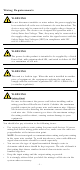
Wiring Requirements WARNING Do not disconnect modules or wires unless the power supply has been switched off or the area is known to be non-hazardous. The devices may only be connected to the supply voltage shown on the type plate. The devices are designed for operation with a Safety Extra-Low Voltage. Thus, they may only be connected to the supply voltage connections and to the signal contact with the Safety Extra-Low Voltages (SELV) in compliance with IEC 60950-1/EN 60950-1.
Package Checklist for EDS-P308 Series The Moxa EDS-P308 Series is shipped with the following items. If any of these items is missing or damaged, please contact your customer service representative for assistance. • • • • Moxa EtherDevice™ Switch EDS-P308 Protective caps for unused ports Quick installation guide (printed) Warranty card Features of EDS-P308 Series High Performance Network Switching Technology • • • • • • • • • 10/100BaseT(X) (RJ45) 100BaseFX (SC type, Multi/Single mode) IEEE802.3/802.
PoE Total Power Budget PoE Output Voltage PoE Output Power PoE Output Current Overload Current Protection (at the port) PoE Pinout Power Rated Voltage Operating Voltage Rated Current Power Consumption Inrush Current Electrical Isolation Heat Dissipation Overload Current Protection (at the input) Reverse Polarity Protection Connection Mechanical Casing Dimensions Weight Installation Environmental Operating Temperature 61.6 W 45.3 VDC @ 48 VDC power input 15.4 W for 802.3af 350 mA for 802.
EDS-P308 Series Panel Layout 1. 2. 3. 4. 5. 6. 7. 8. 9. 10. 11. 12. 13. 14.
EDS-P308 (SC-type) Panel Layout Product models not shown here: EDS-P308-S-SC is identical to EDS-P308-M-SC. EDS-P308-SS-SC is identical to EDS-P308-MM-SC. 1. 2. 3. 4. 5. 6. 7. 8. 9. 10. 11. 12. 13. 14. 15. 16.
Mounting Dimensions Unit = mm (inch) -8-
DIN-Rail Mounting The aluminum DIN-Rail attachment plate should already be fixed to the back panel of the EDS-P308 Series when you take it out of the box. If you need to reattach the DIN-Rail attachment plate, make sure the stiff metal spring is situated towards the top, as shown in the figures below. STEP 1: Insert the top of the DIN-Rail into the slot just below the stiff metal spring. STEP 2: The DIN-Rail attachment unit will snap into place as shown below.
STEP 3: Once the screws are fixed in the wall, insert the four screw heads through the large parts of the keyhole-shaped apertures, and then slide the EDS-P308 downwards, as indicated. Tighten the four screws for added stability. Grounding the EDS-P308 Series Grounding and wire routing help limit the effects of noise due to electromagnetic interference (EMI). Run the ground connection from the ground screw to the grounding surface prior to connecting devices.
EDS-P308 Series’ Alarm Contact The EDS-P308 Series has one alarm contact located on its top panel. For detailed instructions on how to connect the alarm contact power wires to the two middle contacts of the 6-contact terminal block connector, see the Wiring the Alarm Contact section on page 10. A typical scenario would be to connect the Fault circuit to a warning light located in the control room. The light can be set up to switch on when a fault is detected.
LED Indicators The front panel of the EDS-P308 Series contains several LED indicators. The function of each LED is described in the table below. LED Color State Description Power is being supplied to power input PWR1 Power is not being supplied to power Off input PWR1 Power is being supplied to power input On PWR2 Power is not being supplied to power Off input PWR2 When the corresponding PORT alarm is On enabled, and the port’s link is inactive.
Rugged Design • • • Operating temperature range from 0 to 60°C, or extended operating temperature from -40 to 75°C for “-T” models IP30, plastic case DIN-Rail or panel mounting ability Specifications of SPL-24 Technology Standards Interface RJ45 Ports LED Indicators Power Input voltage Output voltage Output current Output Power Connection Overload current Protection Efficiency Mechanical Casing Dimensions Weight Installation Environmental Operating Temperature IEEE802.
SPL-24 Panel Layout 1. 2. 3. 4. 5. 6. 7.
DIN-Rail Mounting for SPL-24 The plastic DIN-Rail attachment plate should already be fixed to the back panel of SPL-24 when you take it out of the box. If you need to reattach the DIN-Rail attachment plate, make sure the stiff metal spring is situated towards the top, as shown in the figures below. STEP 1: Insert the top of the DIN-Rail into the slot. STEP 2: The DIN-Rail attachment unit will snap into place as shown below.
Wiring the SPL-24’s Power Outputs The two left-most contacts of the 3-contact terminal block connector on the SPL-24’s top panel are used for 24 VDC output. Top and front views of one of the terminal block connectors are shown here. STEP 1: Insert the negative/positive DC wires into the V-/V+ terminals. STEP 2: To keep the DC wires from pulling loose, use a small flat-blade screwdriver to tighten the wire-clamp screws on the front of the terminal block connector.